


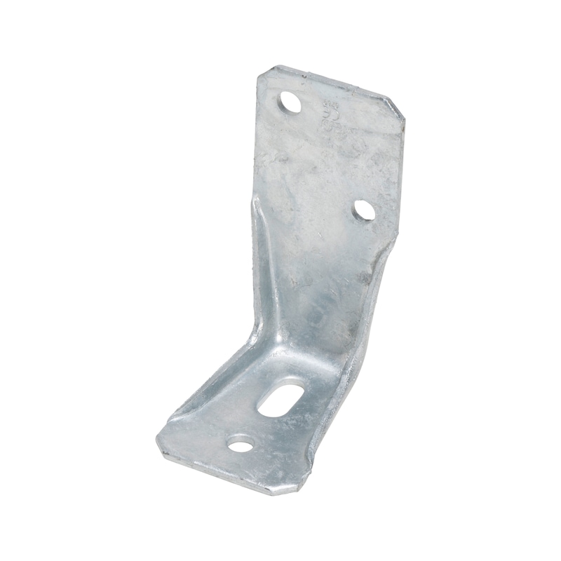

Angle bracket type V-MH with slotted hole
Angle connector type V-MH
ANGL-WOCON-(V-MH)-(TZN)-65X90X137X4MM
Art.-no. 0681632101
EAN 4045989620029

Register now and access more than 125,000 products
- Ideal for use with solid wooden wall constructions thanks to simple screw fastening
- Very high load-bearing capacities
- Sheet metal hot-dip galvanised on both sides (D11 + Z275) in line with EN 10111:1998, thickness 4 mm with subsequent thermal hot-dip galvanisation (55 µm)
- Application in utilisation classes 1, 2 and 3 in line with EN 1995:2013
ETA-14/0274
The general requirements of ETA-14/0274 must be observed.
The general requirements of the applicable anchor approval must be observed.
ETA-14/0274
Datasheets(X)

Tension anchor connection of solid wooden walls, supports or purlins to wood, concrete or steel substrates.
Suitable fasteners:
- ASSY 3.0 post support bracket screw d =10 mm, ASSY 3.0 combination screw d = 10 mm, ASSY plus VG combination screw d = 10 mm
- Recommended dowels for fixing to concrete d = 10 or 12 mm: W-BS; W-FAZ; W-VIZ; WIT-VM 250
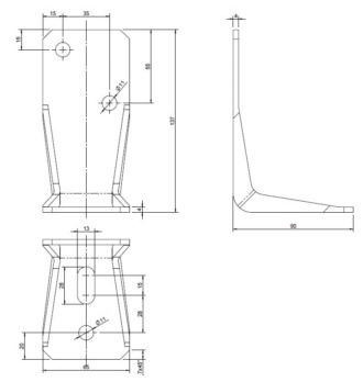 | |
Width x height x depth | 65.0 x 137.0 x 90 mm |
Thickness | 4.0 mm |
Number of D 11 mm holes in main carrier nH | 1 PCS |
Number of D 11 mm holes in subcarrier nJ + main carrier nH | 2 + 1 PCS |
Elongated hole length/ elongated hole width | 28 x 13 mm |
Approval | ETA-08/0214 |
Product weight (per item) | 422.119 g |
Material | Steel |
Surface | Hot dip galvanized |
Weight | 445 g |
Material designation | DD11 |
Number of D 11 mm holes | 3 PCS |
| Load capacity tables angle bracket V slotted/round hole and V-MH | |||||||||
| Characteristic load-bearing capacity and design value of the load-bearing capacity ("short") in load case F1 for Würth angle bracket V slotted hole/round hole and V-MH according to ETA 08/0214 | |||||||||
| Characteristic load-bearing capacity and design value of the load capacity ("short") in load case F1 for angle bracket V slotted hole or round hole and V-MH as tension anchor in a support connection | Characteristic load-bearing capacity and design value of the load capacity ("short") in load case F1 for angle bracket V slotted hole or round hole and V-MH as tension anchor in a support connection | ||||||||
| Size in mm | Ring-shank nails 4x40 mm | ASSY 10x60 mm | KLED | Load-bearing capacity in kN | Size in mm | Ring-shank nails 4x40 mm | ASSY 10x60 mm | KLED | Load-bearing capacity in kN |
| Type V 65x95x90 | 3 | Char. | F1,Rk = 4.60 | Type V 65x95x90 | 3 | Char. | F1,Rk = 9.20 | ||
| Short | F1,Rd = 3.18 | Short | F1,Rd = 6.37 | ||||||
| Type V 65x135x90 | 6 | Char. | F1,Rk = 9.10 | Type V 65x135x90 | 6 | Char. | F1,Rk = 18.30 | ||
| Short | F1,Rd = 6.30 | Short | F1,Rd = 12.67 | ||||||
| Type V 65x285x90 | 9 | Char. | F1,Rk = 13.70 | Type V 65x285x90 | 9 | Char. | F1,Rk = 27.50 | ||
| Short | F1,Rd = 9.48 | Short | F1,Rd = 19.04 | ||||||
| Type V-MH 65x137x90 | 1 | Char. | F1,Rk = 2.90 | Type V-MH 65x137x90 | 1 | Char. | F1,Rk = 11.50 | ||
| Short | F1,Rd = 2.01 | Short | F1,Rd = 7.96 | ||||||
| Tensile force in anchor bolt for wood/concrete: FB,Ed = 1.4 × F1,Ed Tensile force in anchor bolt for wood/wood: FB,Ed = 1.3 × F1,Ed | Tensile force in anchor bolt for wood/concrete: FB,Ed = 0.7 × F1,Ed Tensile force in anchor bolt for wood/wood: FB,Ed = 0.65 × F1,Ed | ||||||||
| Characteristic load-bearing capacity and design value of the load-bearing capacity ("short") in load case F1 for angle bracket V slotted hole or round hole and V-MH as tension anchor in a purlin joint | Characteristic load-bearing capacity and design value of the load-bearing capacity ("short") in load case F1 for two angle brackets V slotted hole or round hole and V-MH as tension anchor in a purlin joint | ||||||||
| Size in mm | Ring-shank nails 4x40 mm | ASSY 10x60 mm | KLED | Load-bearing capacity in kN | Size in mm | Ring-shank nails 4x40 mm | ASSY 10x60 mm | KLED | Load-bearing capacity in kN |
| Type V 65x95x90 | 9 | Char. | F1,Rk = 13.70 | Type V 65x95x90 | 9 | Char. | F1,Rk = 27.40 | ||
| Short | F1,Rd = 9.48 | Short | F1,Rd = 18.97 | ||||||
| Type V 65x135x90 | 14 | Char. | F1,Rk = 21.20 | Type V 65x135x90 | 14 | Char. | F1,Rk = 42.40 | ||
| Short | F1,Rd = 14.68 | Short | F1,Rd = 29.35 | ||||||
| Type V 65x137x90 | 2 | Char. | F1,Rk = 10.90 | Type V 65x137x90 | 2 | Char. | F1,Rk = 21.90 | ||
| Short | F1,Rd = 7.55 | Short | F1,Rd = 15.25 | ||||||
| Tensile force in anchor bolt for wood/concrete: FB,Ed = 1.4 × F1,Ed Tensile force in anchor bolt for wood/wood: FB,Ed = 1.3 × F1,Ed | Tensile force in anchor bolt for wood/concrete: FB,Ed =1, 0.7 × F1,Ed Tensile force in anchor bolt for wood/wood: FB,Ed = 0.65 × F1,Ed | ||||||||
| Notes: For a 11 mm, 12 mm or 13.5 mm hole, a washer with t = 2.5 mm must be used As fasteners, 4x40 mm ring-shank nails in accordance with EN 14592 or 10x60/50 mm ASSY screws in accordance with ETA-11/0190 must be used. ETA 08/0214 specifications must be observed with respect to nail pattern. The prescribed nailing patterns must be used. The load-bearing capacities indicated are for coniferous wood with a characteristic density of ρk ≥ 350 kg/m³. The design value of the load-bearing capacity is calculated as follows: F1,Rd = kmod/γM × F1,Rk with M = 1.3. The design value of the tensile force in the anchor bolt FB,Ed must be calculated using the design value of the tensile force of a tension anchor F1,Ed. | |||||||||
Last viewed

Mounting block

Hexagon bolt, with thread to head and fine thread DIN 961, steel, strength class 10.9, zinc-nickel-plated, transparent passivated (P3E)

Split pin ISO 1234 A4-70 stainless steel, plain

Promotion film production/alteration costs

Trapezoidal blade knife with integrated, magnetic 1/4 inch bit holder and cable stripping tool

Blind rivet, open, with break mandrel and countersunk head ISO 15978, countersunk head, aluminium/steel

Hexagonal bolt ASME B18.2.1, plain GR8 steel
Adjusting ring

Disposable overalls Tychem Tychem

Welder clothing Weldas 33-2300 Fire Fox™ welding jacket