


Angle bracket type V with round hole
Angle connector type V with round hole
ANGL-WOCON-V-ROUNDHOLE-285MM
Art.-no. 5390211285
EAN 4058794749519

Register now and access more than 125,000 products
- Optimum transfer of horizontal forces due to the round hole in the foot plate
- Extremely high load-bearing capacities
- Flexible application
- Sheet metal hot-dip galvanised on both sides (D11 + Z275 (approx. 55 µm)) in accordance with EN 10111:1998, thickness 4 mm
- Use in utilisation class 1, 2 and 3 in accordance with EN 1995:2013
European Technical Approval ETA-14/0274
- Partial nailing is permitted (see load systems dimensioning aid)
- The general requirements of ETA-14/0274 must be observed
- The general requirements of the applicable anchor approval must be observed
- The respective permissible edge distances and spacings of the fasteners must be observed
European Technical Approval ETA-14/0274
Datasheets(X)

For tension anchor connection of wooden walls, supports or purlins to concrete or steel substrates.
Suitable fasteners:
- Ring-shank nails in line with EN 14592: ≥ 4.0 x 40 to 60 mm
- ASSY 4.0 joist hanger screw in line with ETA 11/0190: 5.0 x 35 to 50 mm
- Bolts according to manufacturer's specifications: d = 16 mm
- Recommended anchor for attachment to concrete, d = 16 mm: W-BS; W-FAZ; W-VIZ; WIT-VM 250
- The respective permissible edge distances and spacings of the fasteners must be observed
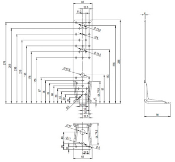 | |
Width x height x depth | 65 x 285 x 90 mm |
Thickness | 4 mm |
Design | Without bar |
Number of D 17 mm holes in main carrier nH | 1 PCS |
Number of D 11 mm holes in main carrier nH | 1 PCS |
Number of D 5 mm holes in subcarrier nJ + main carrier nH | 26 + 2 PCS |
Approval | ETA-14/0274 |
Product weight (per item) | 708.559 g |
Material | Unalloyed quality steel, 1.0332 |
Surface | Hot dip galvanized |
Material designation | DD11 |
Number of D 5 mm holes | 28 PCS |
Number of D 11 mm holes | 1 PCS |
Number of D 13 mm holes | 3 PCS |
| Load capacity tables angle bracket V slotted/round hole and V-MH | |||||||||
| Characteristic load-bearing capacity and design value of the load-bearing capacity ("short") in load case F1 for Würth angle bracket V slotted hole/round hole and V-MH according to ETA 08/0214 | |||||||||
| Characteristic load-bearing capacity and design value of the load capacity ("short") in load case F1 for angle bracket V slotted hole or round hole and V-MH as tension anchor in a support connection | Characteristic load-bearing capacity and design value of the load capacity ("short") in load case F1 for angle bracket V slotted hole or round hole and V-MH as tension anchor in a support connection | ||||||||
| Size in mm | Ring-shank nails 4x40 mm | ASSY 10x60 mm | KLED | Load-bearing capacity in kN | Size in mm | Ring-shank nails 4x40 mm | ASSY 10x60 mm | KLED | Load-bearing capacity in kN |
| Type V 65x95x90 | 3 | Char. | F1,Rk = 4.60 | Type V 65x95x90 | 3 | Char. | F1,Rk = 9.20 | ||
| Short | F1,Rd = 3.18 | Short | F1,Rd = 6.37 | ||||||
| Type V 65x135x90 | 6 | Char. | F1,Rk = 9.10 | Type V 65x135x90 | 6 | Char. | F1,Rk = 18.30 | ||
| Short | F1,Rd = 6.30 | Short | F1,Rd = 12.67 | ||||||
| Type V 65x285x90 | 9 | Char. | F1,Rk = 13.70 | Type V 65x285x90 | 9 | Char. | F1,Rk = 27.50 | ||
| Short | F1,Rd = 9.48 | Short | F1,Rd = 19.04 | ||||||
| Type V-MH 65x137x90 | 1 | Char. | F1,Rk = 2.90 | Type V-MH 65x137x90 | 1 | Char. | F1,Rk = 11.50 | ||
| Short | F1,Rd = 2.01 | Short | F1,Rd = 7.96 | ||||||
| Tensile force in anchor bolt for wood/concrete: FB,Ed = 1.4 × F1,Ed Tensile force in anchor bolt for wood/wood: FB,Ed = 1.3 × F1,Ed | Tensile force in anchor bolt for wood/concrete: FB,Ed = 0.7 × F1,Ed Tensile force in anchor bolt for wood/wood: FB,Ed = 0.65 × F1,Ed | ||||||||
| Characteristic load-bearing capacity and design value of the load-bearing capacity ("short") in load case F1 for angle bracket V slotted hole or round hole and V-MH as tension anchor in a purlin joint | Characteristic load-bearing capacity and design value of the load-bearing capacity ("short") in load case F1 for two angle brackets V slotted hole or round hole and V-MH as tension anchor in a purlin joint | ||||||||
| Size in mm | Ring-shank nails 4x40 mm | ASSY 10x60 mm | KLED | Load-bearing capacity in kN | Size in mm | Ring-shank nails 4x40 mm | ASSY 10x60 mm | KLED | Load-bearing capacity in kN |
| Type V 65x95x90 | 9 | Char. | F1,Rk = 13.70 | Type V 65x95x90 | 9 | Char. | F1,Rk = 27.40 | ||
| Short | F1,Rd = 9.48 | Short | F1,Rd = 18.97 | ||||||
| Type V 65x135x90 | 14 | Char. | F1,Rk = 21.20 | Type V 65x135x90 | 14 | Char. | F1,Rk = 42.40 | ||
| Short | F1,Rd = 14.68 | Short | F1,Rd = 29.35 | ||||||
| Type V 65x137x90 | 2 | Char. | F1,Rk = 10.90 | Type V 65x137x90 | 2 | Char. | F1,Rk = 21.90 | ||
| Short | F1,Rd = 7.55 | Short | F1,Rd = 15.25 | ||||||
| Tensile force in anchor bolt for wood/concrete: FB,Ed = 1.4 × F1,Ed Tensile force in anchor bolt for wood/wood: FB,Ed = 1.3 × F1,Ed | Tensile force in anchor bolt for wood/concrete: FB,Ed =1, 0.7 × F1,Ed Tensile force in anchor bolt for wood/wood: FB,Ed = 0.65 × F1,Ed | ||||||||
| Notes: For a 11 mm, 12 mm or 13.5 mm hole, a washer with t = 2.5 mm must be used As fasteners, 4x40 mm ring-shank nails in accordance with EN 14592 or 10x60/50 mm ASSY screws in accordance with ETA-11/0190 must be used. ETA 08/0214 specifications must be observed with respect to nail pattern. The prescribed nailing patterns must be used. The load-bearing capacities indicated are for coniferous wood with a characteristic density of ρk ≥ 350 kg/m³. The design value of the load-bearing capacity is calculated as follows: F1,Rd = kmod/γM × F1,Rk with M = 1.3. The design value of the tensile force in the anchor bolt FB,Ed must be calculated using the design value of the tensile force of a tension anchor F1,Ed. | |||||||||
Select RAL-colour code
!! NOTE: On-screen visualisation of the colour differs from real colour shade!!
Last viewed

Additional function EPS

Reducing sleeve, with solder connection on both sides EN1254, copper, 5240

Steel spacer stud

Work trousers Kübler Activiq Cotton+ 2250 3421
Low-cut safety shoe S3 Uvex 6502.3

Hexagon Socket Head Cap Screw full thread ISO 4762/DIN 912, steel 12.9, plain, with full thread

Clamping pin/clamping sleeve ISO 8752, spring steel with silver zinc-flake coating

Hexagonal cap nut, high profile DIN 1587, zinc plated 6 steel with thick-layer passivation (VZD)

Hexagon nut, high profile ISO 4033, plain 8 steel

Low-cut safety shoes, S1 Uvex 2 xenova® 9505