


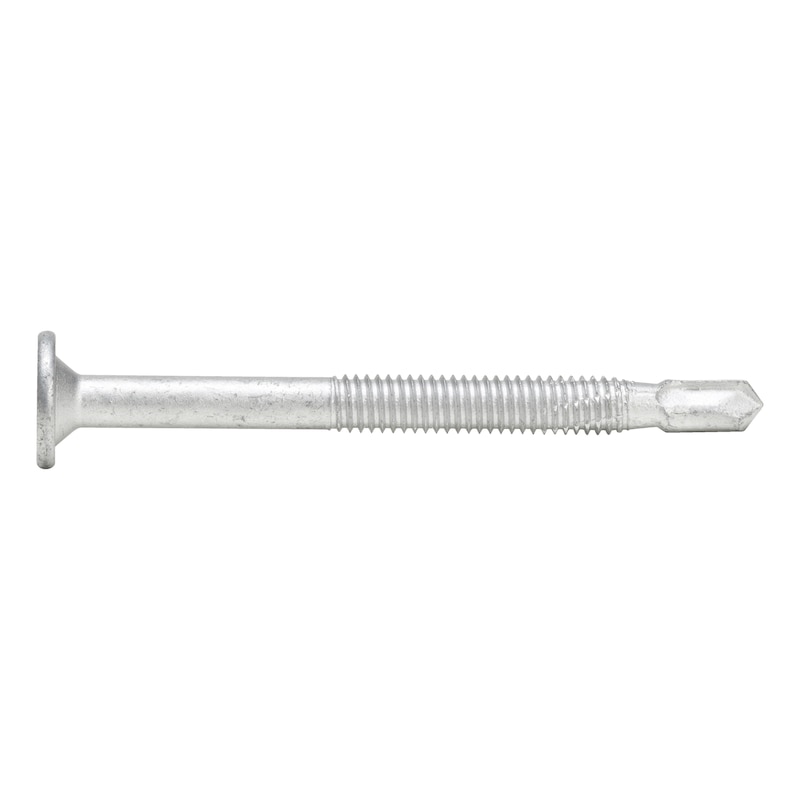


BSD drill rod anchor
Drill rod anchor
DRD-WOALUST-SK-PT-AW40-(RSI)-6,9X113
Art.-no. 5394216113
EAN 4046777066722

Register now and access more than 125,000 products
- Direct screwing into 6 mm thick aluminium extrusion profiles without pre-drilling.
- For aluminium thicknesses over 6 mm and steel connections over 4 mm, pre-drill with a diameter of 6 mm
- Quick and easy, effort-saving screwing-in thanks to integrated forced feed
- High load-bearing capacity and high yield moment thanks to hardened steel quality
EN 14592
The general conditions of EN 14592:2008+A1:2012 and EC5 (EN 1995-1-1:2004 + AC:2006 + A1:2008) must be observed and applied.
EN 14592
Datasheets(X)
CAD data (available after login)

Dowel pins for attaching slotted sheet metal/wood connections made of steel or aluminium.
Direct fitting or placement of BSD drill rod anchor when using aluminium extrusion profiles.
In the case of slotted sheet metal connections made of steel or flexible aluminium sheets, pre-drill through the wood and the metal slotted plate with a diameter of 6 mm.
In the case of multi-shear connections and when using wood with a bulk density of more than 350 kg/m3, position a screw clamp perpendicular to the slotted sheet metal to avoid excessive lateral tension on the wooden support during assembly.
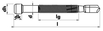 | |
Head type | Round washer head |
Internal drive | AW40 |
Head diameter (dh) | 18 mm |
Head height (dk) | 2.5 mm |
Diameter (d) | 6.93 mm |
Length (l) | 113 mm |
Thread length (lg) | 50 mm |
Shape of tip | Drilling tip |
Material | Hardened steel |
Drill tip length | 15 mm |
Surface | Flake zinc silver |
Product weight (per item) | 36.000 g |
Yield moment | 43.5 Nm |
Approval | EN 14592 |
| Load capacity table of drill rod anchors BSD | ||||||||
| Table 4: Conversion factors fr for bulk densities rk ≥ 350 kg/m³ | ||||||||
| Strength class | GL24c | C30 | GL24h | GL28c, GL30c | C24, GL32c | GL28h | GL30h | GL32h |
| Bulk density in kg/m³ | 365 | 380 | 385 | 390 | 400 | 425 | 430 | 440 |
| fr | 1,02 | 1,04 | 1,05 | 1,06 | 1,07 | 1,10 | 1,11 | 1,12 |
| PLEASE NOTE: These are guides for planning purposes. The values must be calculated for each project by authorised persons. | ||||||||
| Load capacity table of drill rod anchors BSD | |||||||||
| Table 3: Load capacity against shear force per rod anchor for connections with 1, 2 and 3 plates with a maximum slot thickness ts = 10 mm | |||||||||
| b | Rod anchor d x l | Plates | bnet | a = 0° | a = 90° | ||||
| mm | mm | Unt. | mm | ta mm | ti mm | Fv,Rk mm | ta mm | ti mm | Fv,Rk mm |
| 80 | 6.9 x 73 | 1 | 70 | 35 | – | 8,37 | 35 | – | 6,73 |
| 2 | 60 | ≤ 21 | ≥ 18 | 9,77 | ≤ 26 | ≥ 8 | 6,72 | ||
| 3 | 50 | ≤ 21 | ≥ 4 | 7,93 | ≤ 25 | ≥ 0 | 5,45 | ||
| 100 | 6.9 x 93 | 1 | 90 | 45 | – | 9,14 | 45 | – | 7,09 |
| 2 | 80 | ≤ 21 | ≥ 38 | 13,5 | ≤ 26 | ≥ 28 | 9,26 | ||
| 3 | 70 | ≤ 21 | ≥ 14 | 11,6 | ≤ 26 | ≥ 9 | 7,99 | ||
| 120 | 6.9 x 113 | 1 | 110 | 55 | – | 10,2 | 55 | – | 7,67 |
| 2 | 100 | 15 ≤ ta ≤ 21 | 58 ≤ ti ≤ 70 | 17,1 | ≤ 26 | ≥ 48 | 11,8 | ||
| 3 | 90 | ≤ 21 | ≥ 24 | 15,3 | ≤ 26 | ≥ 19 | 10,5 | ||
| 140 | 6.9 x 133 | 1 | 130 | 65 | – | 11,3 | 65 | – | 8,39 |
| 2 | 120 | 25 | 70 | 20,3 | 18 ≤ ta ≤ 26 | 68 ≤ ti ≤ 84 | 14,3 | ||
| 3 | 110 | ≤ 21 | ≥ 34 | 19,0 | ≤ 26 | ≥ 29 | 13,1 | ||
| 160 | 6.9 x 153 | 1 | 150 | 75 | – | 12,6 | 75 | – | 9,18 |
| 2 | 140 | 34 | 72 | 21,3 | 27 | 86 | 16,7 | ||
| 3 | 130 | ≤ 21 | ≥ 44 | 22,7 | ≤ 26 | ≥ 39 | 15,6 | ||
| 180 | 6.9 x 173 | 1 | 170 | 85 | – | 13,0 | 85 | – | 10,0 |
| 2 | 160 | 44 | 72 | 22,1 | 37 | 86 | 17,6 | ||
| 3 | 150 | ≤ 21 | ≥ 54 | 26,4 | ≤ 26 | ≥ 49 | 18,1 | ||
| 200 | 6.9 x 193 | 1 | 190 | 95 | – | 13,0 | 95 | – | 10,7 |
| 2 | 180 | 54 | 72 | 23,1 | 47 | 86 | 18,0 | ||
| 3 | 170 | 15 ≤ ta ≤ 21 | 64 ≤ ti ≤ 70 | 30,1 | ≤ 26 | ≥ 59 | 20,7 | ||
| 220 | 6.9 x 213 | 1 | 210 | 105 | – | 13,0 | 105 | – | 10,8 |
| 2 | 200 | 65 | 70 | 24,2 | 57 | 86 | 18,6 | ||
| 3 | 190 | 24 | 71 | 33,2 | ≤ 26 | ≥ 69 | 23,2 | ||
| 240 | 6.9 x 233 | 1 | 230 | 115 | – | 13,0 | 115 | – | 10,8 |
| 2 | 220 | 74 | 72 | 25,5 | 26 | 12 | 19,3 | ||
| 3 | 210 | 34 | 71 | 34,4 | 20 ≤ ta ≤ 26 | 79 ≤ ti ≤ 85 | 25,7 | ||
| The bearing capacities given are for coniferous wood C24 (rk = 350 kg/m³). For other strength classes, the load capacities can be multiplied by the factors in Table 4. | |||||||||
| PLEASE NOTE: These are guides for planning purposes. The values must be calculated for each project by authorised persons. | |||||||||
| Load capacity table of drill rod anchors BSD | ||||||||
| If using multiple rod anchors in succession in the direction of the grain, the load capacity of the connection must be calculated using the effective number of rod anchors: nef = n90 x n0,ef,a. The effective number of rod anchors depends on the number n0 of rod anchors placed in succession in the direction of the grain, on the axis distance a1 and on the angle between the load and grain. The following applies to load/grain angles of a = 0°: nef = n90 x n0,ef,0°. The following applies to load/grain angles of = 90°: n0,ef,90° = n0 and therefore nef = n90 x n0. At load/grain angles a 90°, the effective number of rod anchors in the direction of the grain can be calculated using the following equation: n0,ef,a = n0,ef,0° x (90° - a)/90° + n0 x / 90° If the wood is prevented from splitting by a reinforcement perpendicular to the direction of the grain, e.g. by using ASSY plus VG screws, the formula nef = n90 x n0 can be used for calculation regardless of the load/grain angle. | Table 6: Effective number of rod anchors n0,ef,0° depending on the distance a1 and the number of rod anchors n0 for a = 0° | |||||||
| a1 in mm | 30 | 40 | 50 | 60 | 80 | 100 | 120 | |
| n0 | 2 | 1,42 | 1,52 | 1,61 | 1,69 | 1,81 | 1,92 | 2,00 |
| 3 | 2,04 | 2,20 | 2,32 | 2,43 | 2,61 | 2,76 | 2,89 | |
| 4 | 2,65 | 2,85 | 3,01 | 3,15 | 3,38 | 3,58 | 3,74 | |
| 5 | 3,24 | 3,48 | 3,68 | 3,85 | 4,14 | 4,37 | 4,58 | |
| 6 | 3,81 | 4,10 | 4,33 | 4,54 | 4,87 | 5,15 | 5,39 | |
| 7 | 4,38 | 4,71 | 4,98 | 5,21 | 5,60 | 5,92 | 6,20 | |
| 8 | 4,94 | 5,31 | 5,61 | 5,88 | 6,31 | 6,68 | 6,99 | |
| 9 | 5,49 | 5,90 | 6,24 | 6,53 | 7,02 | 7,42 | 7,77 | |
| 10 | 6,04 | 6,49 | 6,86 | 7,18 | 7,72 | 8,16 | 8,54 | |
| Load capacity table of drill rod anchors BSD | |||||||||
| Table 2: Load capacity against shear force per rod anchor for connections with 1, 2 and 3 plates with a maximum slot thickness ts = 8 mm | |||||||||
| b | Rod anchor d x l | Plates | bnet | a = 0° | a = 90° | ||||
| mm | mm | Unt. | mm | ta mm | ti mm | Fv,Rk mm | ta mm | ti mm | Fv,Rk mm |
| 80 | 6.9 x 73 | 1 | 72 | 36 | – | 8,43 | 36 | – | 6,75 |
| 2 | 64 | ≤ 21 | ≥ 22 | 10,5 | ≤ 26 | ≥ 12 | 7,23 | ||
| 3 | 56 | ≤ 21 | ≥ 7 | 9,03 | ≤ 26 | ≥ 2 | 6,22 | ||
| 100 | 6.9 x 93 | 1 | 92 | 46 | – | 9,23 | 46 | – | 7,14 |
| 2 | 84 | ≤ 21 | ≥ 42 | 14,2 | ≤ 26 | ≥ 32 | 9,77 | ||
| 3 | 76 | ≤ 21 | ≥ 17 | 12,7 | ≤ 26 | ≥ 12 | 8,75 | ||
| 120 | 6.9 x 113 | 1 | 112 | 56 | – | 10,3 | 56 | – | 7,74 |
| 2 | 104 | 17 ≤ ta ≤ 22 | 60 ≤ ti ≤ 70 | 17,9 | ≤ 26 | ≥ 52 | 12,3 | ||
| 3 | 96 | ≤ 21 | ≥ 27 | 16,4 | ≤ 26 | ≥ 22 | 11,3 | ||
| 140 | 6.9 x 133 | 1 | 132 | 66 | – | 11,5 | 66 | – | 8,46 |
| 2 | 124 | 27 | 70 | 20,7 | 20 ≤ ta ≤ 26 | 72 ≤ ti ≤ 84 | 14,8 | ||
| 3 | 116 | ≤ 21 | ≥ 37 | 20,1 | ≤ 26 | ≥ 32 | 13,8 | ||
| 160 | 6.9 x 153 | 1 | 152 | 76 | – | 12,7 | 76 | – | 9,27 |
| 2 | 144 | 36 | 72 | 21,5 | 29 | 86 | 16,9 | ||
| 3 | 136 | ≤ 21 | ≥ 47 | 23,8 | ≤ 26 | ≥ 42 | 16,4 | ||
| 180 | 6.9 x 173 | 1 | 172 | 86 | – | 13,0 | 86 | – | 10,1 |
| 2 | 164 | 46 | 72 | 22,3 | 39 | 86 | 17,6 | ||
| 3 | 156 | ≤ 21 | ≥ 57 | 27,5 | ≤ 26 | ≥ 52 | 18,9 | ||
| 200 | 6.9 x 193 | 1 | 192 | 96 | – | 13,0 | 96 | – | 10,8 |
| 2 | 184 | 56 | 72 | 23,3 | 49 | 86 | 18,1 | ||
| 3 | 176 | 18 ≤ ta ≤ 21 | 67 ≤ ti ≤ 70 | 31,2 | ≤ 26 | ≥ 62 | 21,4 | ||
| 220 | 6.9 x 213 | 1 | 212 | 106 | – | 13,0 | 106 | – | 10,8 |
| 2 | 204 | 67 | 70 | 24,5 | 59 | 86 | 18,7 | ||
| 3 | 196 | 27 | 71 | 33,8 | 13 ≤ ta ≤ 26 | 72 ≤ ti ≤ 85 | 24,0 | ||
| 240 | 6.9 x 233 | 1 | 232 | 116 | – | 13,0 | 116 | – | 10,8 |
| 2 | 224 | 76 | 72 | 25,7 | 26 | 12 | 19,5 | ||
| 3 | 216 | 37 | 71 | 34,5 | 23 ≤ ta ≤ 26 | 82 ≤ ti ≤ 85 | 26,5 | ||
| The bearing capacities given are for coniferous wood C24 (rk = 350 kg/m³). For other strength classes, the load capacities can be multiplied by the factors in Table 4. | |||||||||
| PLEASE NOTE: These are guides for planning purposes. The values must be calculated for each project by authorised persons. | |||||||||
| Load capacity table of drill rod anchors BSD | |||||||||
| Table 1: Load capacity against shear force per rod anchor for connections with 1, 2 and 3 plates with a maximum slot thickness ts = 6 mm | |||||||||
| b | Rod anchor d x l | Plates | bnet | a = 0° | a = 90° | ||||
| mm | mm | Unt. | mm | ta mm | ti mm | Fv,Rk mm | ta mm | ti mm | Fv,Rk mm |
| 80 | 6.9 x 73 | 1 | 74 | 37 | – | 8,49 | 37 | – | 6,78 |
| 2 | 68 | ≤ 21 | ≥ 26 | 11,2 | ≤ 26 | ≥ 16 | 7,74 | ||
| 3 | 62 | ≤ 21 | ≥ 10 | 10,1 | ≤ 26 | ≥ 10 | 6,98 | ||
| 100 | 6.9 x 93 | 1 | 94 | 47 | – | 9,33 | 47 | – | 7,19 |
| 2 | 88 | ≤ 21 | ≥ 46 | 14,9 | ≤ 26 | ≥ 36 | 10,3 | ||
| 3 | 82 | ≤ 21 | ≥ 20 | 13,8 | ≤ 26 | ≥ 15 | 9,51 | ||
| 120 | 6.9 x 113 | 1 | 114 | 57 | – | 10,4 | 57 | – | 7,81 |
| 2 | 108 | 20 | 68 | 18,6 | 12 ≥ ta ≤ 26 | 56 ≤ ti ≤ 84 | 12,8 | ||
| 3 | 102 | ≤ 21 | ≥ 30 | 17,5 | ≤ 26 | ≥ 25 | 12,1 | ||
| 140 | 6.9 x 133 | 1 | 134 | 67 | – | 11,6 | 67 | – | 8,54 |
| 2 | 128 | 29 | 70 | 21,0 | 24 | 80 | 15,3 | ||
| 3 | 122 | ≤ 21 | ≥ 40 | 21,2 | ≤ 26 | ≥ 35 | 14,6 | ||
| 160 | 6.9 x 153 | 1 | 154 | 77 | – | 12,7 | 77 | – | 9,35 |
| 2 | 148 | 38 | 72 | 21,6 | 31 | 86 | 17,2 | ||
| 3 | 142 | ≤ 21 | ≥ 50 | 24,9 | ≤ 26 | ≥ 45 | 17,1 | ||
| 180 | 6.9 x 173 | 1 | 174 | 87 | – | 13,0 | 87 | – | 10,2 |
| 2 | 168 | 48 | 72 | 22,5 | 41 | 86 | 17,7 | ||
| 3 | 162 | 11 ≤ ta ≤ 21 | 60 ≤ ti ≤ 70 | 28,6 | ≤ 26 | ≥ 55 | 19,7 | ||
| 200 | 6.9 x 193 | 1 | 194 | 97 | – | 13,0 | 97 | – | 10,8 |
| 2 | 188 | 58 | 72 | 23,5 | 51 | 53 | 18,2 | ||
| 3 | 182 | 21 | 70 | 32,3 | ≤ 26 | ≥ 65 | 22,2 | ||
| 220 | 6.9 x 213 | 1 | 214 | 107 | – | 13,0 | 107 | – | 10,8 |
| 2 | 208 | 69 | 70 | 24,7 | 61 | 86 | 18,9 | ||
| 3 | 202 | 30 | 71 | 34,2 | 16 ≥ ta ≤ 26 | 75 ≤ ti ≤ 85 | 24,7 | ||
| 240 | 6.9 x 233 | 1 | 234 | 117 | – | 13,0 | 117 | – | 10,8 |
| 2 | 228 | 78 | 72 | 25,8 | 71 | 86 | 19,7 | ||
| 3 | 222 | 40 | 71 | 34,8 | 26 | 85 | 27,3 | ||
| The bearing capacities given are for coniferous wood C24 (rk = 350 kg/m³). For other strength classes, the load capacities can be multiplied by the factors in Table 4. | |||||||||
| PLEASE NOTE: These are guides for planning purposes. The values must be calculated for each project by authorised persons. | |||||||||
| Load capacity table of drill rod anchors BSD | ||||||
| Table 5: Minimum distances according to EN 1995-1-1 Table 8.5 depending on the load/grain angle a | ||||||
| a | a1 | a2 | a3,t | a3,c | a4,t | a4,c |
| 0 | 35 | 21 | 80 | 40 | 21 | 21 |
| 10 | 35 | 40 | 21 | |||
| 20 | 34 | 40 | 21 | |||
| 30 | 33 | 40 | 21 | |||
| 40 | 32 | 52 | 23 | |||
| 50 | 30 | 62 | 25 | |||
| 60 | 28 | 70 | 26 | |||
| 70 | 26 | 76 | 27 | |||
| 80 | 24 | 79 | 28 | |||
| 90 | 21 | 80 | 28 | |||
| KEY | |
| ti | Minimum middle wood width |
| ta | Minimum side wood thickness |
| Plates | Number of plates |
| bnet | Net cross-section width of the wooden component minus the slots |
| b | Cross-section width of the wooden component |
| Fv,Rk | Characteristic load capacity against shear force of a drill rod anchor BSD |
| Rated load capacity of a rod anchor: Fv,Rd = Fv,Rk × kmod/1.3 | |
| Calculation basis | |
| Sheet steel/wood connections with drill rod anchors are calculated in accordance with EN 1995-1-1 Section 8.6. Characteristic values of drill rod anchors: d = 6.9 mm, My,Rk = 43.5 Nmm The rod anchors must be pre-drilled to their nominal diameter and screwed in at one end flush with the surface at an angle of less than 90° to the direction of the grain. | |
| Prerequisites for using the tabulated values | |
| Sheet steel/wood connection with steel plates inside Sheet steel: strength min. S235, minimum sheet thickness 3 mm for sufficient bearing stress capacity of sheet steel with edge distances of e1 ≥ 3 x d0 and e2 ≥ 1.5 x d0. The load/grain angle a is 0° or 90°. The specified load capacities are not valid for other angles. The rod anchors must be arranged perpendicular to the direction of the grain. The rod anchors must be screwed in flush with the surface on one side. The specified thickness of the outer and inner wooden components (ta and ti) must be observed. The bearing capacities given are for coniferous woods with a characteristic bulk density pk of 350 kg/m³. Connections with rod anchors should contain at least 2 drill rod anchors. Connections using one drill rod anchor only have half the calculated load capacity. The minimum distances in line with EN 1995-1-1 Table 8.5. | |
| PLEASE NOTE: These are guides for planning purposes. The values must be calculated for each project by authorised persons. | |
Select RAL-colour code
!! NOTE: On-screen visualisation of the colour differs from real colour shade!!
Last viewed

Fully threaded hexagonal bolt and fine thread ISO 8676, 10.9 steel with silver zinc-flake coating (ZFSHL)

Hole saw spring

Cantilever rack, welded with roll-off protection

pias® drilling screw, round head with collar and AW drive

Welder clothing Weldas Lava Brown™ welding gaiters

Hexagon Socket Head Cap Screw ISO 4762, natural polyamide 6.6

Threaded fitting DIN 976, zinc plated 8.8 steel with thick-layer passivation (VZD)

Compartment separator

Dry sandpaper strips
Hole saw accessories Ruko 113217 carbide ejector pin