Concrete screw W-BS-T temporary
Concrete screw W-BS-T, temporary
CONCSCR-(W-BS-T)-(A2K)-WS15-5-10X80
Art.-no. 5929910080
EAN 4056807619514


Register now and access more than 125,000 products
- Quick and easy installation
- Immediate load-bearing capacity
- Very secure installation
- Low material costs as re-usable
- No installation torque required
DIBt National technical approval for cracked and uncracked concrete Z-21.8-2090 for the temporary attachment of construction site equipment
The screw and the thread must be checked for visual defects with the test sleeve supplied before every reuse.
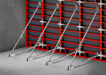
Oblique struts in formwork construction
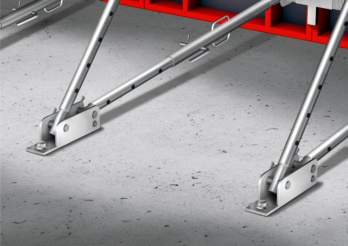
Oblique struts in formwork construction
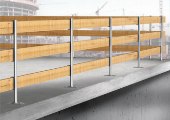
Construction site railings
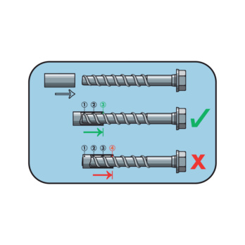
The concrete screw should be checked for wear before every use. The concrete screw may only be re-used when more than three thread turns can be inserted into the sleeve.
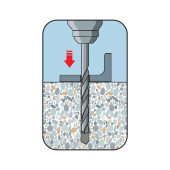
Create the drill hole
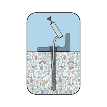
Clean the drill hole
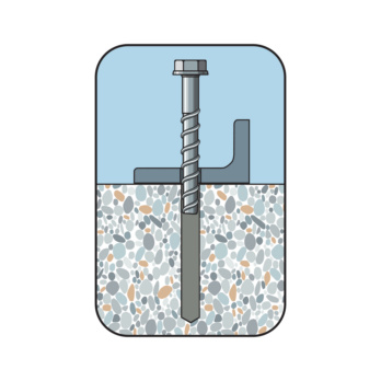
Place screw
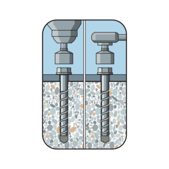
Screw in the screw
DIBt National technical approval for cracked and uncracked concrete Z-21.8-2090 for the temporary attachment of construction site equipment
Datasheets(X)
Temporary fixings of construction site facilities, such as props, slanted props, scaffolding or fall protection such as railings
- In reinforced and non-reinforced concrete
- In cracked and uncracked concrete
- For normal weight concrete of strength classes C20/25 to C50/60
- In fresh concrete from a concrete compressive strength of fck, cube ≥ 10 N/mm²
 | |
Anchor size | 10 mm |
Anchor length (l) | 80 mm |
Attachment height (t fix 1) | 5 mm |
Material | Steel |
Surface | Zinc plated |
External drive | WS15 |
Nominal drill-bit diameter (d 0) | 10 mm |
Drill hole depth (h 1) | 85 mm |
Type description | W-BS-T |
Attachment height (t fix 1-2-3) | 5 / - / - mm |
| Performance data in concrete | |||||||||
| Anchor diameter [mm] | 10 | 12 | 14 | ||||||
| Length of anchor in concrete hnom≥ [mm] | 75 | 75 | 90 | 75 | 90 | 115 | |||
| Admissible centric tension load1) and admissible shear load1) of an individual anchor | Cracked and uncracked concrete compressive strength fck,cube ≥ 10 N/mm² | Fadm [kN] | 4 | 4 | 8 | 4 | 8 | 10 | 11,3 |
| Cracked and uncracked concrete compressive strength fck,cube ≥ 15 N/mm² | 4,6 | 4,6 | 8,6 | 4,6 | 8,6 | 12 | 14 | ||
| Cracked and uncracked concrete compressive strength fck,cube ≥ 20 N/mm² | 5,3 | 5,3 | 9,3 | 5,3 | 9,3 | 13,3 | 16 | ||
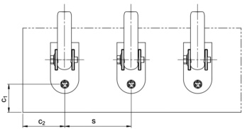
| Minimum spacing | s [mm] | 320 | 320 | 390 | 320 | 390 | 500 | ||
| Minimum edge distance in load direction | c1 [mm] | 105 | 105 | 130 | 105 | 130 | 165 | ||
| Minimum edge distance transverse to load direction | c2 [mm] | 160 | 160 | 195 | 160 | 195 | 250 | ||
| Minimum member thickness | hmin ≥ [mm] | 150 | 150 | 195 | 150 | 195 | 200 | 225 | |
| Drill hole depth | h1 ≥ [mm] | 85 | 85 | 100 | 85 | 100 | 125 | ||
| Through hole in the component being connected | df ≤ [mm] | 14 | 16 | 18/222) | |||||
| Nominal drill diameter | d0 [mm] | 10 | 12 | 14 | |||||
| Diameter of cutting edges | dcut ≤ [mm] | 10,45 | 12,5 | 14,5 | |||||
| 1) The partial safety factor of γF = 1.5, as regulated in the approval, is taken into account 2) df = 22 mm only applies to the 14x130 version with collar | |||||||||
Select RAL-colour code
!! NOTE: On-screen visualisation of the colour differs from real colour shade!!


