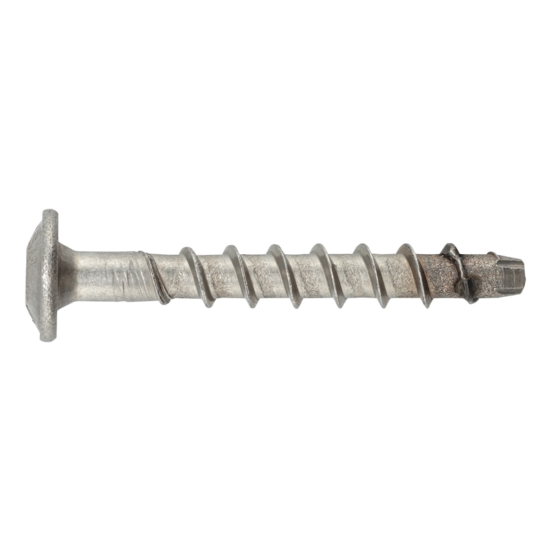
Concrete screw with pan head W-BS 2/A4 type P
Concrete screw W-BS 2 type P A4 stainless steel
ANC-(W-BS 2/P)-A4-TX30-45-65-6X100
Art.-no. 5931246100
EAN 4065746448321


Register now and access more than 125,000 products
- The new thread geometry ensures smooth screwing into the concrete and thus greater efficiency
- The fastest type of fastening for medium loads
- Three effective anchorage depths allow flexible application
- Attachments can be adjusted up to twice retrospectively, for example to be able to align anchor plates (observe installation instructions)
- Minimum spacing and edge distances due to very low expansion effect
European technical assessment ETA-22/0123 for fixing point option 1, cracked and non-cracked concrete:
- Static and quasi-static effects (∅6)
- Seismic effect, performance category C1 (∅6)
- Fire resistance R30, R60, R90, R120
When installing with a tangential impact screwdriver, the recommended maximum rated torque must be observed. When used outdoors, the drill hole can be sealed with WIT-BS injectable mortar.
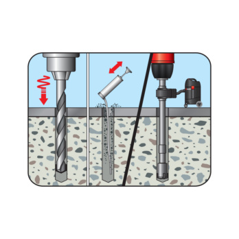 Drill the hole
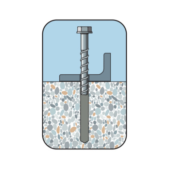
Place screw
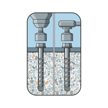
Screw in the screw
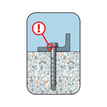
Considered installed when the head is close fitting
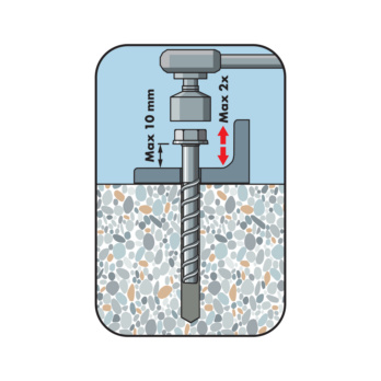
Screw out the screw max. 2x each by max. 10 mm. Underlay. Screw in
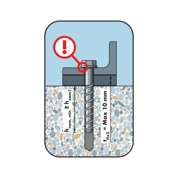
Considered installed when the head is close fitting. Lining max. 10 mm. The required embedment depth must be maintained as a minimum
European technical assessment ETA-22/0123 for fixing point option 1, cracked and non-cracked concrete:
- Static and quasi-static effects (∅6)
- Seismic effect, performance category C1 (∅6)
- Fire resistance R30, R60, R90, R120
Datasheets(X)
Fixing point with approval (∅6):
In normal weight concrete C20/25 to C50/60 (cracked and non-cracked concrete)
Pan head with attractive head geometry, ideally suited for fastening medium loads in concrete:
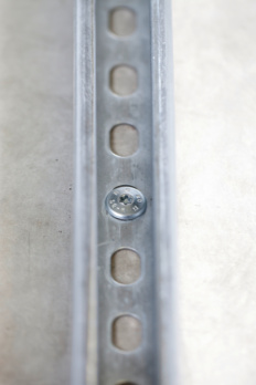
- Fastening of e.g. mounting rails, panels, sheets, fire protection panels, handrails, metal profiles, brackets, wooden substructures etc. in in-place installation
- Mounting under seismic conditions in earthquake areas
- Mounting in areas under exposure to fire
W-BS 2/A4 (A4 stainless steel) can be used in dry indoor conditions, outdoors (including in industrial atmospheres and close to the sea) or in wet rooms, provided that no particularly aggressive conditions are present
For use in concrete < C20/25 and pressure-resistant natural stone (without approval)
Anchor size | 6 mm |
Anchor length (l) | 100 mm |
Attachment height (t fix 1) | 65 mm |
Attachment height (t fix 2) | 55 mm |
Attachment height (t fix 3) | 45 mm |
Thread diameter | 7.5 mm |
Nominal drill-bit diameter (d 0) | 6 mm |
Drill hole depth (h 1.1) | 40 mm |
Drill hole depth (h 1.2) | 50 mm |
Drill hole depth (h 1.3) | 60 mm |
Embedding depth (h nom1) | 35 mm |
Embedding depth (h nom2) | 45 mm |
Embedding depth (h nom3) | 55 mm |
Internal drive | TX30 |
Material | Stainless steel A4 |
Surface | Plain |
Head diameter | 15 mm |
Through-hole in the component to be connected (d f) | 8 mm |
Head type | Pan head |
| Performance data in concrete - fixing point according to ETA-22/0123 | |||||
| Anchor size [mm] | 6 | ||||
| Nominal length of thread engagement | hnom [mm] | 353) | 45 | 55 | |
| Admissible centric tension load1) on an individual anchor without the influence of the edge distance | Tensile zone (cracked concrete C20/252), s ≥ 3 hef c ≥ 1.5 hef) | Nadm [kN] = C20/252) | 1.2 | 0.7 | 1.4 |
| Compressive zone (uncracked concrete C20/252), s ≥ 3 hef c ≥ 1.5 hef) | 1.7 | 1.9 | 4.0 | ||
| Admissible shear load1) on an individual anchor without the influence of the edge distance | Tensile zone (cracked concrete C20/252), c ≥ 10 hef) | Vadm [kN] = C20/252) | 2.0 | 4.0 | 4.0 |
| Compressive zone (uncracked concrete C20/252), c ≥ 10 hef) | 2.9 | 4.0 | 4.0 | ||
| Admissible bending moment | Madm. [Nm] | 6.2 | |||
| Admissible load under seismic activity performance categories C1 and C2, see European technical assessment ETA-22/0123 | C1 | x | x | ||
| C2 | |||||
| Admissible load when exposed to fire (R30, R60, R90, R120), see European technical assessment ETA-22/0123 | |||||
| 1) The partial safety factors of the resistances γM regulated in the approval/assessment and a partial safety factor of the effects of γF = 1.4 have been taken into account. Please refer to the appropriate guidelines, e.g. DIN EN 1992-4, for information on combining tensile and shear loads, the influence of the edge distance and groups of anchors 2) The concrete has normal reinforcement. Higher values are possible for higher concrete compressive strengths 3) Only statically indeterminate non-load-bearing systems (anchors in a redundant non-structural system) according to EN 1992-4, only in dry indoor conditions | |||||
| Installation parameters in concrete | ||||
| Anchor size [mm] | 6 | |||
| Nominal length of thread engagement | hnom [mm] | 351) | 45 | 55 |
| Minimum spacing | smin [mm] | 35 | ||
| Minimum edge distance | cmin [mm] | 35 | ||
| Minimum member thickness | hmin [mm] | 80 | 100 | |
| Thread diameter | dth [mm] | 7.5 | ||
| Nominal drill ∅ | d0 ≤ [mm] | 6 | ||
| ∅ of cutting edges | dcut ≤ [mm] | 6.40 | ||
| Drill hole depth | h0 ≥ [mm] | 40 | 50 | 60 |
| Through hole in the component being connected | df ≤ [mm] | 8 | ||
| Internal drive | TX30 | |||
| Screw-head height | hn [mm] | 3.5 | ||
| Head diameter | dsk [mm] | 15 | ||
| Max. rated torque of tangential impact screwdriver | Timp,max [Nm] | 160 | ||
| 1) Only statically indeterminate non-load-bearing systems (anchors in a redundant non-structural system) according to EN 1992-4 and only in dry indoor conditions | ||||


