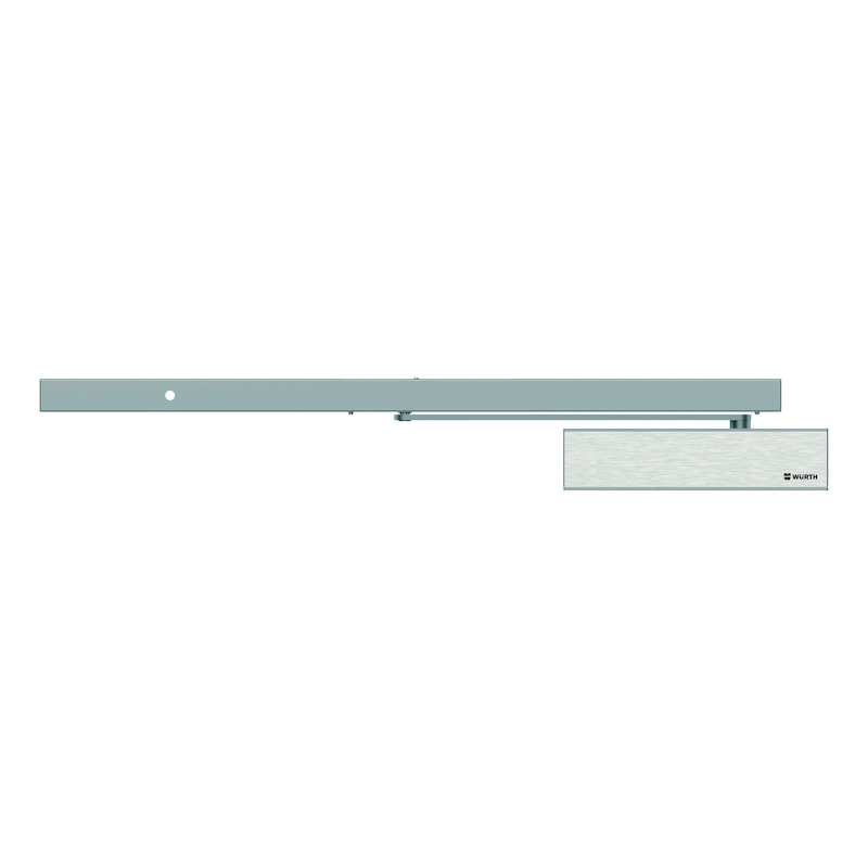
Electromagnetic hold-open device, single-leaf Non-hinge side With GTS 640 G and integrated smoke detector
EFR system with GTS 640G + integrated RSZ
HOLDOPNDEV-EFR-GTS640G-DIN/L-SILVER
Art.-no. 0688003640
EAN 4061975572455

Register now and access more than 125,000 products
The system fulfils the latest testing principles
- Switch-off time of magnets with alarm min. 3 seconds
- Override capacity of system/door, can be set to below 80 N (for use without manual button)
- Line monitoring for ceiling detectors and manual button
All electronic components in the sliding rail are fully pre-mounted, wired and the assemblies checked ex works
- This enables faster assembly without faults
- Smoke detector with contamination indicator and automatic calibration for preventing false alarms
Quick mounting of the sliding rail using only two screws
- Same drilling pattern as with sliding rails for the door closer
Easy routing of the connecting cable through cable duct integrated into the sliding rail
The use of a manual switch is not absolutely necessary, but is recommended. The opening angle of the door leaf must be limited using a suitable floor door stopper.
The operator of the systems is required to commission the system after initial installation, to test it monthly for the first 12 months, and afterwards, if there are no functional defects, to test it every 3 months and perform a service once a year. Akademie Würth offers seminars in this respect.
Delivery time approx. 10 working days.

Dimensions subject to change. Subject to technical changes.
Datasheets(X)
A hold-open device is an electrical device that is used to keep fire protection closures open. The door leaf can be held in the open position until the device is either tripped manually or automatically via the smoke detector in the event of a fire or power failure, then the door closes. For single-leaf fire, smoke protection and panic doors made of metal or wood.
Area of application | Hold-open device, Object area, Private area |
Suitable for | Fire protection doors, Smoke protection doors, Panic doors |
Suitable for number of doors | 1 |
Fire protection certified | Yes |
Suitable for barrier-free construction according to DIN 18040 | Yes |
Colour | White aluminium RAL 9006, Stainless steel, matt |
Colour slide rail | Silver |
Gloss level | Matt |
Suitable for min./max. door width | 860-1250 mm |
DIN direction | DIN L |
Mounting option | Opposite hinge side: standard mounting, With assembly base plate |
Opening angle | 110 Degree |
Min./max. door closer size | 2-5 |
Material | Aluminium / stainless steel / plastic / steel |
Surface | Lacquered |
Surface of the body | Lacquered |
Surface of the rail | Lacquered |
Suitable for min./max. door thickness | 40-72 mm |
Locking range | 80° - 110° |
Closing speed | Infinitely adjustable by valve 130° - 0 ° |
Closing delay | Infinitely adjustable by valve 120 ° - 70 ° opposite hinge side normal assembly |
Latching speed | Infinitely adjustable by valve 10° - 0 ° |
Back-check action | Infinitely variable adjustable from 70 ° |
Min./max. temperature conditions | -15 to 40 °C |
Nominal voltage | 230 V/AC |
Standards | EN 1154:1996 + A1:2002, EN 1155:1997 + A1:2002, EN 16034, EN 16035, DIN 18040-1, DIN 18040-2, SPEC 1104 |
EC declaration of conformity (CE) | Yes |
Environmental Product Declaration | Yes |
Construction product | Yes |
| max. opening angle (in degrees) across X and Z | ||||||
| X Z | 1 | 2 | 4 | 6 | 8 | 10 |
| 60 | 125 | 124 | 123 | 122 | 121 | 120 |
| 65 | 122 | 121 | 120 | 119 | 118 | 117 |
| 70 | 119 | 119 | 118 | 117 | 116 | 115 |
| 75 | 117 | 116 | 115 | 114 | 113 | 112 |
| 80 | 114 | 114 | 113 | 112 | 111 | 110 |
| 85 | 112 | 111 | 110 | 109 | 108 | 107 |
| 90 | 109 | 109 | 108 | 107 | 106 | 105 |
| 95 | 107 | 107 | 106 | 105 | 104 | 103 |
| Note: Max. holding angle is 3-5° below the max. opening angle | ||||||
| Non-hinge side installation with lintel casing bracket R (DIN L mirror-image) |
| 1: Hole for electrical connection (230 V AC), 2: Recommended distance, taken into account here |
| max. opening angle (in degrees) across X and Z | ||||||
| X Z | -6.5 | -5 | -3 | 0 | 5 | 10 |
| 60 | 128 | 127 | 126 | 125 | 122 | 119 |
| 65 | 125 | 125 | 123 | 122 | 119 | 117 |
| 70 | 123 | 122 | 121 | 119 | 117 | 114 |
| 75 | 120 | 119 | 118 | 117 | 114 | 112 |
| 80 | 117 | 117 | 116 | 114 | 112 | 109 |
| 85 | 115 | 114 | 113 | 112 | 109 | 107 |
| 90 | 112 | 112 | 111 | 109 | 107 | 105 |
| 95 | 110 | 109 | 108 | 107 | 105 | 103 |
| Note: Max. holding angle is 3-5° below the max. opening angle | ||||||
| Non-hinge side installation with adapter profile 40 DIN R (DIN L mirror-image) |
| 1: Hole for electrical connection (230 V AC), 2: Additional connections (optional) |
| max. opening angle (in degrees) across X and Z | ||||||
| X Z | -1.5 | 0 | 2 | 5 | 10 | 15 |
| 60 | 128 | 127 | 126 | 125 | 122 | 119 |
| 65 | 125 | 125 | 123 | 122 | 119 | 117 |
| 70 | 123 | 122 | 121 | 119 | 117 | 114 |
| 75 | 120 | 119 | 118 | 117 | 114 | 112 |
| 80 | 117 | 117 | 116 | 114 | 112 | 109 |
| 85 | 115 | 114 | 113 | 112 | 109 | 108 |
| 90 | 112 | 112 | 111 | 109 | 107 | 105 |
| 95 | 110 | 109 | 108 | 107 | 105 | 103 |
| Note: Max. holding angle is 3-5° below the max. opening angle | ||||||
| Classification key in accordance with DIN EN 1154: 1996 + A1:2002 | |||||
| 3/4 | 8 | 2 - 5 | 1 | 1 | 4 |
| Direct installation on hinge side DIN R (DIN L mirror-image) |
| 1: Hole for electrical connection (230 V AC), 2: Additional connections (optional) |
Select RAL-colour code
!! NOTE: On-screen visualisation of the colour differs from real colour shade!!


