


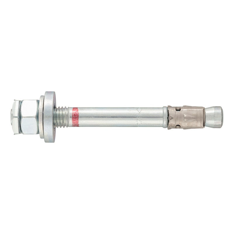


Fixanchor W-FAZ PRO dynamic/S
Fixanchor W-FAZ PRO dynamic steel zinc plated
ANC-(W-FAZ PRO DYN/S)-(A2K)-10-M10X100
Art.-no. 5930241010
EAN 4065746533874


Register now and access more than 125,000 products
- Bolt anchors for individual attachment under fatigue loading (dynamic) in concrete
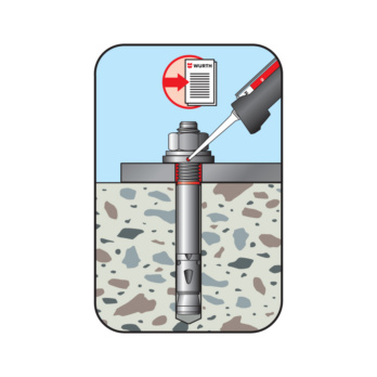
- Simple, fast and secure mounting with dynamic set
- Facilitates maximum efficiency in use
- Facilitates mounting with minimum axle and edge spacing
- High performance even with static and seismic influence and fire exposure
European Technical Assessment ETA-20/0486
- Individual attachment under fatigue-relevant cyclic stress
European Technical Assessment ETA-20/0229
- Static or quasi-static effects
- Seismic exposure, performance categories C1 and C2
- Fire load R30, R60, R90, R120
Load bearing behaviour under fire load (ETK uniform temperature time curve) - Expert opinion no. GS 6.1/20-018-1
- Fire duration 180 minutes
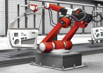 Robot systems (fatigue-related influences)
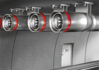 Tunnel ventilation (fatigue-related influences)
 Conveyor belts (fatigue-related influences)
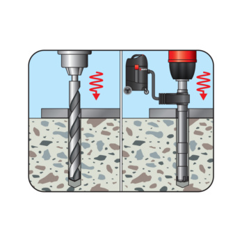
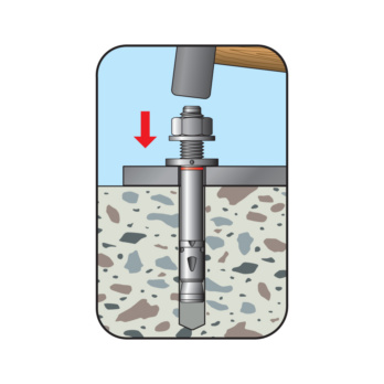
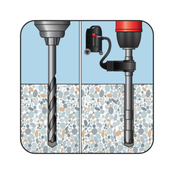
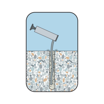
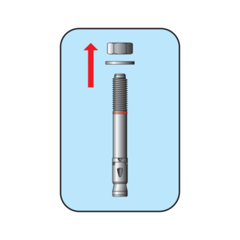
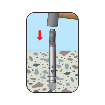
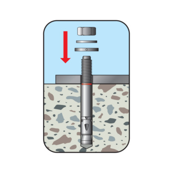
Create the drill hole
European Technical Assessment ETA-20/0486
- Individual attachment under fatigue-relevant cyclic stress
European Technical Assessment ETA-20/0229
- Static or quasi-static effects
- Seismic exposure, performance categories C1 and C2
- Fire load R30, R60, R90, R120
Load bearing behaviour under fire load (ETK uniform temperature time curve) - Expert opinion no. GS 6.1/20-018-1
- Fire duration 180 minutes
Datasheets(X)

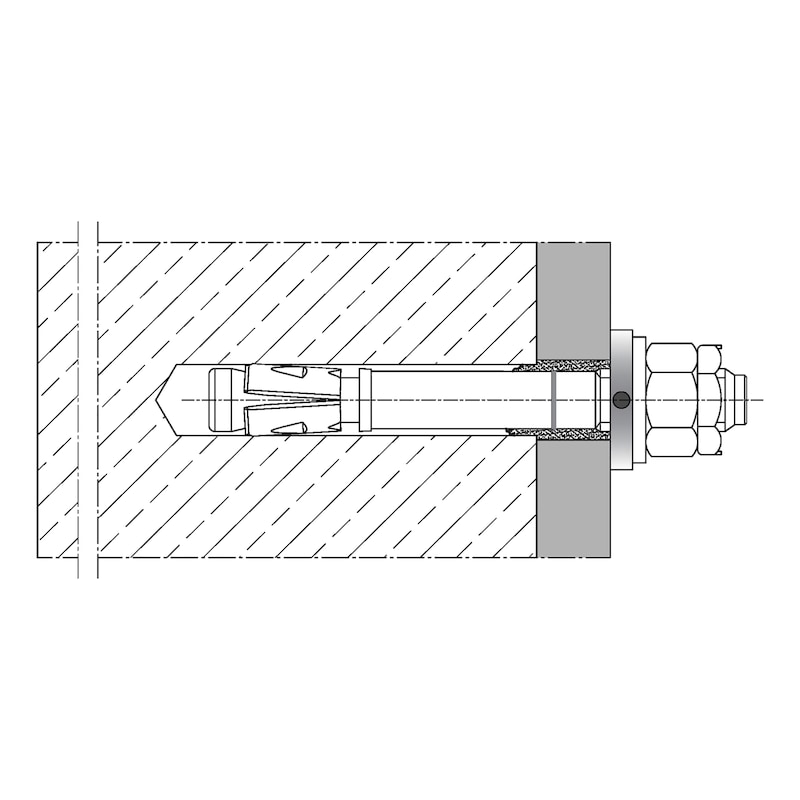
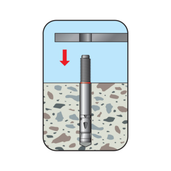
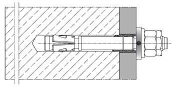
Individual attachment under fatigue loading in pre-positioned or push-through installation
Single mounting under static or quasi-static, seismic influence and fire load
Base material:
- Reinforced and non-reinforced standard concrete without fibres
- Cracked or non-cracked concrete
- Strength class C20/25 to C50/60
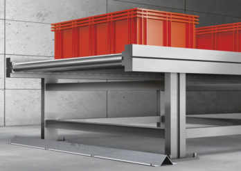
Heavy-duty fastenings for dynamic loads in concrete
Suitable for anchoring attachment parts under fatigue-relevant cyclical stress, e.g. crane tracks, slewing cranes, fans, machines, robots, conveyor systems, lift guide rails, traffic control systems along railways, roads and in tunnels.
 | |
Metric anchor diameter | M10 |
Anchor length (l) | 100 mm |
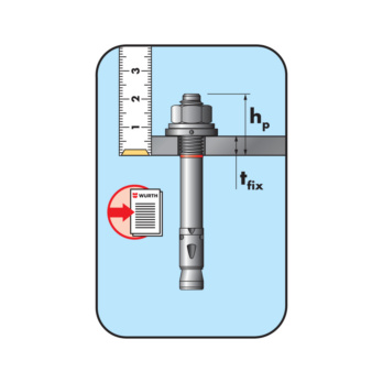
Min./max. height of the fixture (t fix) | 5-10 mm |
Attachment height (t fix) | 10 mm |
Effective anchoring depth (h ef) | 60 mm |
Disc diameter x disc thickness | 20 x 2 mm |
Width across flats | 17 mm |
Nominal drill-bit diameter (d 0) | 10 mm |
Drill hole depth (h 1) | 71 mm |
Material | Steel / steel |
Surface | Zinc plated |
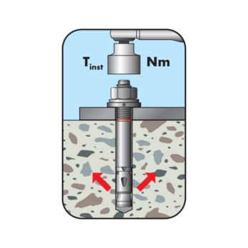
Torque during anchoring (T inst) | 40 Nm |
Through-hole in the component to be connected (d f) | 12 mm |
Thread type x anchor diameter x thread length (L th) | M10 x 26 |
Approval | ETA-20/0486, ETA-20/0229 |
Seismology C1 | Yes |
Seismology C2 | Yes |
| Performance data | |||||
| Performance data of an individual anchor without axis and edge influence under fatigue-relevant cyclic stress according to ETA-20/0486 | |||||
| Anchor diameter | [mm] | M10 | M12 | M16 | |
| Effective anchoring depth | hef | [mm] | 60 | 70 | 85 |
| Individual attachment in cracked and non-cracked concrete | |||||
| Permissible centric tension load in concrete ≥ C20/25 1) | Nperm | [kN] | 3,4 | 4,6 | 7,2 |
| Permissible transverse load in concrete ≥ C 20/25 1) | Vperm | [kN] | 1,9 | 3,0 | 5,6 |
| Static and quasi-static load, fire load and seismic load according to European Technical Assessment ETA-20/0229 | |||||
| 1) Permissible loads in accordance with EN 1992-4 of an individual anchor without influence of axis and edge distances. The overall safety factor has been taken into account. | |||||
| Installation parameters1) | |||||
| Anchor diameter | [mm] | M10 | M12 | M16 | |
| Effective anchoring depth | hef ≥ | [mm] | 60 | 70 | 85 |
| Minimum component thickness | hmin ≥ | [mm] | 90 | 105 | 127,5 |
| Minimum axis distance | smin | [mm] | 40 | 50 | 65 |
| Minimum edge spacing | cmin | [mm] | 45 | 55 | 65 |
| Nominal drill ∅ | d0 | [mm] | 10 | 12 | 16 |
| ∅ of cutting edges | dcut ≤ | [mm] | 10,45 | 12,5 | 16,5 |
| Drill hole depth 2) | h0 ≥ | [mm] | hef +9 | hef +10 | hef +14 |
| h1 ≥ | [mm] | hef +11 | hef +13 | hef +17 | |
| Through hole in the attachment | df ≤ | [mm] | 12 | 14 | 18 |
| Width across flats hexagon nut | AF | [mm] | 17 | 19 | 24 |
| With across flats locking nut | AF | [mm] | 17 | 19 | 24 |
| Torque while installing anchor | Tinst = | [Nm] | 40 | 60 | 110 |
| Overhang | hp | [mm] | 21.5 + tfix | 25.5 + tfix | 29.5 + tfix |
| Height of the hexagon nut | tnut | [mm] | 8 | 10 | 13 |
| ∅ Washer | dw x tw | [mm] | 20 x 2 | 24 x 2.5 | 30 x 3 |
| ∅ Filling washer x height | dWIT-SHB x tWIT-SHB | [mm] | 26 x 5 | 28 x 5 | 34 x4 |
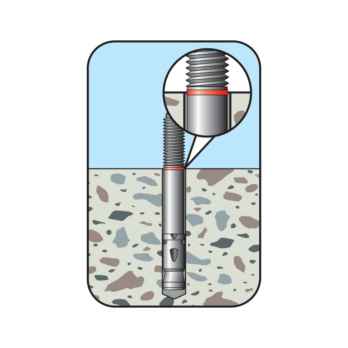
| 1) For anchor groups and anchoring close to the edge, the combinations of the minimum values (component thickness, axis and edge distances) and the associated loads must be determined in accordance with the calculation methods of European Technical Assessment (ETA-20/0486). 2) If the maximum clamping thickness tfix,max is not fully utilised, the drill hole depth can be increased by the appropriate dimension and the dowel lowered. For push-through installation, h1,d=h1+tfix,max. For pre-positioned installation, h1,v=h1+(tfix,max - tfix). The specified tfix,min must be observed. The end of the thread must always be above the concrete surface. | |||||
Select RAL-colour code
!! NOTE: On-screen visualisation of the colour differs from real colour shade!!
Last viewed

Cheese head screw With hexagon socket

Hexagon head serrated screw with flange W-0273, steel 100, plain

Cutting disc Klingspor A 924 R SPECIAL
Safety boots S3 Steitz VD 3800 BOA SST SF

System housing for hinged door 8.6/574x603 mm

Crimp cable lug, push connector fully insulated polyamide

Anchor nail 26°
Diamond cutting disc Klingspor DT 300 U Extra

Combi vehicle sponge

Abrasive cloth roll Klingspor KL 361 JF