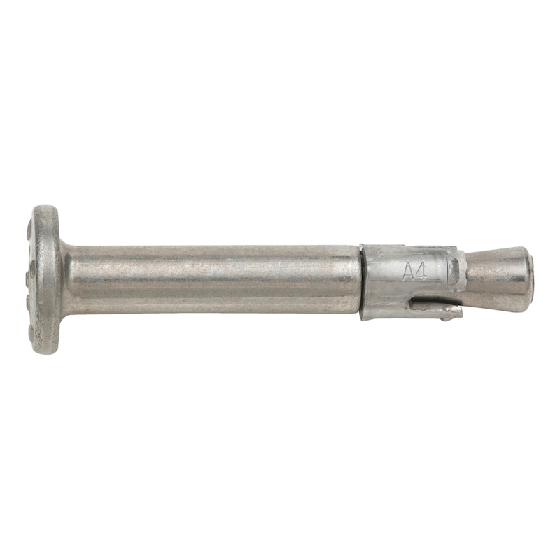
Hammer-in anchor W-NA-K/HCR With nail head
Nail anchor W-NA-K/HCR
ANC-(W-NA-K/HCR)-(HCR)-30-6X69
Art.-no. 0905381030
EAN 4053479287706


Register now and access more than 125,000 products
- Quick and easy installation
- Less drilling required thanks to reduced effective anchorage depth of 25 mm
- Easy insertion: Simply hammer in - no torque required
- No special drills or setting tools required
- Push-through installation
- Very low edge distances and spacings possible
- Elegant, attractive design
- Torque-controlled expanding anchor — expands when subjected to load
- Multiple attachment of non-load-bearing systems in concrete: European Technical Approval ETA-11/0339
- Fire resistance: R30, R60, R90, R120 (anchoring base: concrete C20/25 to C50/60): Technical Report TR 020 "Evaluation of anchorages in concrete concerning resistance to fire" (included in ETA-11/0339)
- Fire-tested in line with the ZTV tunnel fire curve in the cracked tension zone
Not possible to order S-24!
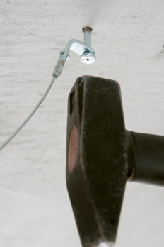
The nail anchor offers the benefits of a bolt anchor while also being easy to install; the nail anchor is simply knocked into the drill hole through the attached part
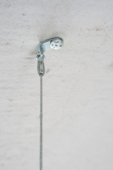
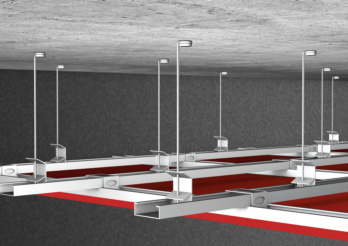 Suspended ceilings
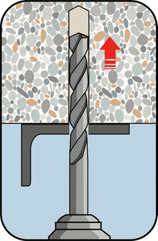
Create the drill hole
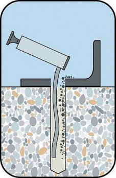
Clean the drill hole
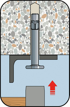
Insert the nail anchor through the component and knock it in
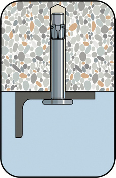
Drive in the nail anchor until it is flush
- Multiple attachment of non-load-bearing systems in concrete: European Technical Approval ETA-11/0339
- Fire resistance: R30, R60, R90, R120 (anchoring base: concrete C20/25 to C50/60): Technical Report TR 020 "Evaluation of anchorages in concrete concerning resistance to fire" (included in ETA-11/0339)
- Fire-tested in line with the ZTV tunnel fire curve in the cracked tension zone
Datasheets(X)
CAD data (available after login)
Anchors in a redundant non-structural system in non-load-bearing systems with approval in cracked concrete (tensile zone) and uncracked concrete (compression zone)
- E.g. lightweight ceiling cladding and suspended ceilings, metal profiles, perforated strips, wire hangers, vernier hangers, wooden strips, wooden laths, square timbers etc.
- For use in reinforced or non-reinforced normal weight concrete with a concrete compressive strength of min. C12/15 and max. C50/60 in accordance with EN 206-1:2000-12
Can be used in areas where there is a very high risk of corrosion (e.g. indoor swimming pool atmospheres, road tunnels, poorly ventilated car parks, or with parts that are immersed in seawater or in coastal atmospheres)
Anchor diameter | 6 mm |
Anchor length (l) | 69 mm |
Min./max. height of the fixture (t fix) | 30-35 mm |
Nominal drill-bit diameter (d 0) | 6 mm |
Effective anchoring depth (h ef) | 30 mm |
Effective anchoring depth reduced (h ef, red) | 25 mm |
Drill hole depth (h 0) | 40 mm |
Drill hole depth reduced (h 0, red) | 35 mm |
Minimum component thickness (h min) | 80 mm |
Through-hole in the component to be connected (d f) | 7 mm |
Material | High corrosion-resistant steel, 1.4529, X1NiCrMoCuN25-20-7 |
Surface | Plain |
| Performance data | |||
| Anchor diameter [mm] | 6 (hef [mm] = 25) | 6 (hef [mm] = 30) | |
| Anchors in concrete in a non-structural system based on a redundant design (for all load directions) for c ≥ 100 mm and s ≥ 200 mm | Fadm [kN] ≥ C12/15 | 1,4 | 1.93) |
| Fadm [kN] ≥ C20/25 and ≤ C50/60 1) | 2.13) | 2.83) | |
| Anchors in concrete in a non-structural system based on a redundant design (for all load directions) for c ≥ 50 mm and s ≥ 100 mm | Fadm [kN] ≥ C12/15 | 0,7 | 1,0 |
| Fadm [kN] ≥ C20/25 and ≤ C50/60 1) | 1,0 | 1,2 | |
| Permissible bending moment | Madm [Nm] | 7,3 | 7,3 |
| Admissible load when exposed to fire (Technical Report TR 020) For spacing and edge distances, see European Technical Approval ETA-11/0339 | R30; Fadm [kN] 2) | 0,6 | 0,9 |
| R60; Fadm [kN] 2) | 0,6 | 0,8 | |
| R90; Fadm [kN] 2) | 0,6 | 0,6 | |
| R120; Fadm [kN] 2) | 0,5 | 0,5 | |
| 1) The partial safety factors of the resistances regulated in the approval and a partial safety factor of the actions of γF = 1.4 have been taken into account. Please refer to the European Technical Approval Guidelines (ETAG), Annex C, for information on combining tensile and shear loads, influence of the edge distance and groups of anchors. 2) The partial safety factors for load capacity under exposure to fire of γM,fi = 1.0 as recommended in the approval and the partial safety factor of the effects of γF = 1.0 have been taken into account. | |||
| Characteristic values | ||
| Minimum member thickness | hmin [mm] | 80 |
| Effective anchorage depth | hef [mm] | 30 |
| Nominal drill ∅ | d0 [mm] | 6 |
| Diameter of cutting edges | dcut ≤ [mm] | 6,4 |
| Drill hole depth | h1 ≥ [mm] | 40 |
| Through hole in the component being connected | df ≤ [mm] | 7 |


