Hammer-in anchor W-SD with internal thread
Impact anchor W-SD female thread
DWL-(W-SD/6L-IG)-(A2K)-M8
Art.-no. 0905700200
EAN 4011231852319


Register now and access more than 125,000 products
Stop bits must be used
Anchors and stop bits form a perfectly coordinated system. This system unit prevents installation errors and ensures attachment as stipulated in the approval.
- Small drill hole depth
- Small drill hole diameter
- Low minimum component thickness (hmin = 80 mm)
- Immediate load-bearing capacity – no waiting after insertion
- Easy insertion — no installation torque
- Anchorage via friction locking – distance-controlled expanding anchor
- Multiple attachment of non-load-bearing systems in concrete: European Technical Approval ETA-07/0138
- Dimensioned in accordance with the European Technical Approval Guidelines (ETAG) for "Metal Anchors for Use in Concrete", Appendix C, measurement process C
- Fire resistance (anchoring base: concrete C20/25 to C50/60): R30, R60, R90, R120 (W-SD M6L, W-SD M8): Technical Report TR 020 "Evaluation of anchorages in concrete concerning resistance to fire" (included in ETA-07/0138)
- The partial safety factors of the resistances regulated in the approval and a partial safety factor of the effects of yF = 1.4 have been taken into account. Please refer to the European Technical Approval Guidelines (ETAG), Appendix C, for information on combining tensile and transverse loads, edge influence and groups of anchors.
- The partial safety factors for load-bearing capacity on exposure to fire of yM,fi = 1.0 as recommended in the approval and the partial safety factor of the effects of yF = 1.0 have been taken into account.
- Carbide masonry drills must comply with the specifications set out in the code of practice of the German institute of building technology (DIBt) and the Association of German Tool Manufacturers (FWI) on the characteristics, requirements and tests of masonry drills with carbide cutting inserts used to drill holes for fixing anchors. Würth hammer drills meet the specifications set out in the code of practice.
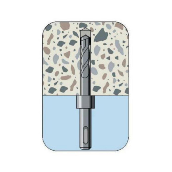 Create the drill hole
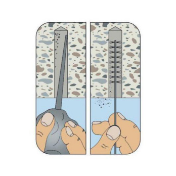 Clean the drill hole
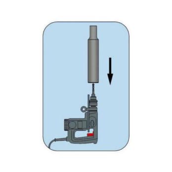 Put setting tool onto stop bit
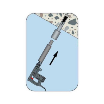 Install anchor
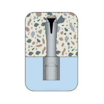 Installation status
- Multiple attachment of non-load-bearing systems in concrete: European Technical Approval ETA-07/0138
- Dimensioned in accordance with the European Technical Approval Guidelines (ETAG) for "Metal Anchors for Use in Concrete", Appendix C, measurement process C
- Fire resistance (anchoring base: concrete C20/25 to C50/60): R30, R60, R90, R120 (W-SD M6L, W-SD M8): Technical Report TR 020 "Evaluation of anchorages in concrete concerning resistance to fire" (included in ETA-07/0138)
Datasheets(X)
- Can be used for multiple attachment of non-load-bearing systems in concrete, anchorage of lightweight ceiling cladding and suspended ceilings
- Multiple attachment of non-load-bearing systems: Anchorage with European Technical Approval in cracked concrete (tension zone) and non-cracked concrete (compression zone)
- The anchor has European Technical Approval for use in reinforced or non-reinforced standard concrete with a strength class of min. C20/25 and max. C50/60 in accordance with EN 206:2000-12
- The anchor may be used for anchorages with predominantly static loads or quasi-static loads
- W-SD (galvanised steel) can be used in dry indoor areas
- Suitable for attaching ceiling structures with threaded rods, suspension of threaded rods, cable and pipe clamps, cable and ventilation ducts etc.
Anchor length (l) (l) | 52.5 mm |
Nominal drill-bit diameter (d 0) | 6.0 mm |
Type description | W-SD 6L-IG |
Centre-to-centre distance with multiple attachment (s cr) | 200 mm |
Edge clearance for multiple attachment (c cr) | 150 mm |
Minimum component thickness (h min) | 80 mm |
Drill hole depth (h 1) | 42 mm |
Connection-thread length (l th) | 15 mm |
Length of protrusion (l p) | 15 mm |
Effective anchoring depth (h ef) | 36 mm |
Female thread | 8 mm |
| Performance data | |||
| Anchor diameter [mm] | 6L | 8 | |
| Anchors in a redundant non-structural system in concrete (for all load directions) | Fadm [kN] ≥ C20/25 and ≤ C50/601) | 1,4 | 1,4 |
| Admissible bending moment | Madm [Nm] | 4,4 | 10,3 |
| Admissible load when exposed to fire (Technical Report TR 020) For axis and edge distances, see European Technical Approval ETA-07/0138 | R30; Fadm [kN]2) | 0,8 | 1,4 |
| R60; Fadm [kN]2) | 0,5 | 1,0 | |
| R90; Fadm [kN]2) | 0,3 | 0,6 | |
| R120; Fadm [kN]2) | 0,2 | 0,4 | |
| Characteristic values | |||
| Minimum axis distance | scr [mm] | 200 | 200 |
| Minimum edge distance | ccr [mm] | 150 | 150 |
| Minimum member thickness | hmin [mm] | 80 | 80 |
| Effective anchorage depth | hef [mm] | 36 | 36 |
| Nominal drill diameter3) | d0 [mm] | 6,0 | 8,0 |
| Drill cutting diameter3) | dcut ≤ [mm] | 6,4 | 8,45 |
| Drill hole depth | h1 = [mm] | 42 | 43 |
| Through hole in the component being connected | df ≤ [mm] | 7 (male thread only) | 9 (male thread only) |
Select RAL-colour code
!! NOTE: On-screen visualisation of the colour differs from real colour shade!!


