Heavy-duty anchor W-TM type A with internal thread
Heavy-duty anchor W-TM steel zinc plated type A
ANC-(W-TM/S-A)-(A2K)-200-M8X51


Register now and access more than 125,000 products
- Minimal effort required to insert anchor
- Immediate load-bearing capacity — no waiting
- No setting tools required
- Can be set flush with surface: Attached parts can be removed/remounted at any time
- Triple expansion sleeve to ensure even expansion and load distribution
- Suitable for bolts and screws with a metric thread
- Applying the specified torque during the anchoring process ensures secure installation
- Load-controlled/torque-controlled expanding galvanised steel anchor in sizes M6–M12
- Cotter-pin installation
ETA-10/0255 for individual attachment, Option 7, non-cracked concrete, galvanised steel, M6–M12; dimensioned in accordance with the European Technical Approval Guidelines (ETAG) for "Metal Anchors for Use in Concrete", Appendix C, measurement process A
The partial safety factors of the resistances regulated in the approval and a partial safety factor of the actions of yF = 1.4 have been taken into account. Please refer to the European Technical Approval Guidelines (ETAG), Appendix C, for information on combining tensile and transverse loads, influence of the edge distance and groups of anchors.
The concrete has normal reinforcement. Higher values are possible for higher concrete compressive strengths.
Compliant with approval if screws and threaded rods with acceptance test certificate 3.1 in accordance with EN 10204:2004 are proven to be the required material and to possess the mechanical properties stipulated in ETA-10/0255
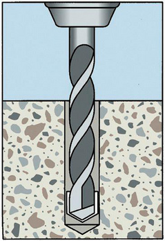
Create the drill hole
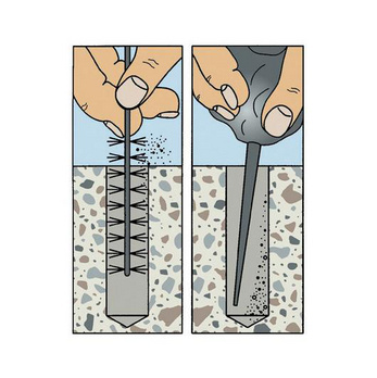
Clean the drill hole
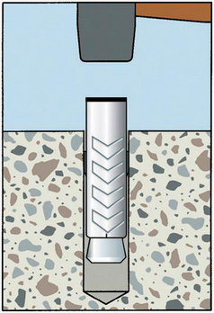
Knock in anchor until flush
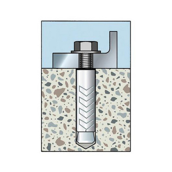
Mount component
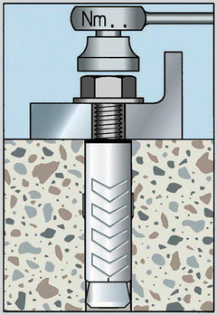
Apply torque
ETA-10/0255 for individual attachment, Option 7, non-cracked concrete, galvanised steel, M6–M12; dimensioned in accordance with the European Technical Approval Guidelines (ETAG) for "Metal Anchors for Use in Concrete", Appendix C, measurement process A
Datasheets(X)
- Can be used for medium to heavy loads
- Suitable for fastening: Transfer lines on the ground requiring installation flush with the surface; steel structures, metal profiles, brackets, base plates, cable conduits, piping, mounting rails etc.
- The anchor with European Technical Assessment for anchorage in reinforced or unreinforced normal weight concrete with a strength class of min. C20/25 and max. C50/60 in accordance with EN 206:2000-12
- Can be used in concrete
- The anchor may be used for anchorages with predominantly static loads or quasi-static loads
- Individual fixing point: Anchorage with European Technical Assessment in uncracked concrete
- May only be used in dry indoor conditions
Anchor diameter | 8 mm |
Anchor length (l) | 51 mm |
Max. attachment height (t fix) | 200 mm |
Nominal drill-bit diameter (d 0) | 12 mm |
Drill hole depth (h 1) | 61 mm |
Effective anchoring depth (h ef) | 44.5 mm |
Through-hole in the component to be connected (d f) | 9 mm |
Material | Steel |
Surface | Zinc plated |
| Anchor diameter [mm] | M6 | M8 | M10 | M12 | ||
| Admissible centric tension load1) on an individual anchor without influence of the edge distance type A + type S | Compressive zone (uncracked concrete C20/252)), s ≥ 3 hef, c ≥ 1.5 hef | Nadm [kN] = C20/252) | 3,6 | 4,1 | 5,4 | 9,5 |
| Admissible shear load1) on an individual anchor without influence of the edge distance type A + type S | Compressive zone (uncracked concrete C20/252)), s ≥ 3 hef, c ≥ 1.5 hef | Vadm [kN] = C20/252) | 4,6 | 7,1 | 8,9 | 19,3 |
| Admissible bending moment type A + type S | Madm [Nm] | 7,0 | 17,1 | 34,2 | 59,9 | |
| 1) The partial safety factors of the resistances regulated in the approval and a partial safety factor of the actions of YF = 1.4 have been taken into account. Please refer to the European Technical Approval Guidelines (ETAG), Appendix C, for information on combining tensile and shear loads, the influence of the edge distance and groups of anchors. 2) The concrete has normal reinforcement. Higher values are possible for higher concrete compressive strengths. 3) Compliant with approval if screws and threaded rods with acceptance test certificate 3.1 in accordance with EN 10204:2004 are proven to be the required material and to possess the mechanical properties stipulated in ETA-10/0255. 4) Type S: If a lower fixture thickness is required, make a deeper drill hole accordingly. | ||||||
| Minimum member thickness | hmin ≥ [mm] | 135 | 135 | 140 | 160 |
| Minimum spacing | smin ≥ [mm] | 65 | 90 | 135 | 165 |
| Minimum edge distance | cmin ≥ [mm] | 45 | 70 | 85 | 115 |
| Spacing | scr,N [mm] | 119 | 134 | 155 | 189 |
| Edge distance | ccr,N [mm] | 60 | 67 | 78 | 95 |
| Effective anchorage depth | hef [mm] | 39,5 | 44,5 | 51,5 | 63,0 |
| Nominal drill diameter | d0 [mm] | 10 | 12 | 14 | 18 |
| Diameter of cutting edges | dcut ≤ [mm] | 10,45 | 12,5 | 14,5 | 18,5 |
| Drill hole depth4) | h1 ≥ [mm] | 55 | 61 | 70 | 85 |
| Through hole in the component being connected | df ≤ [mm] | 7 | 9 | 12 | 14 |
| Torque during anchoring (type A + type S) | Tinst [Nm] | 10 | 25 | 40 | 75 |
| Torque during anchoring (type O + type H) | Tinst [Nm] | 5 | 12 | 20 | 35 |
Select RAL-colour code
!! NOTE: On-screen visualisation of the colour differs from real colour shade!!


