Helical insert W.TEC® INSERT COIL Screw Grip
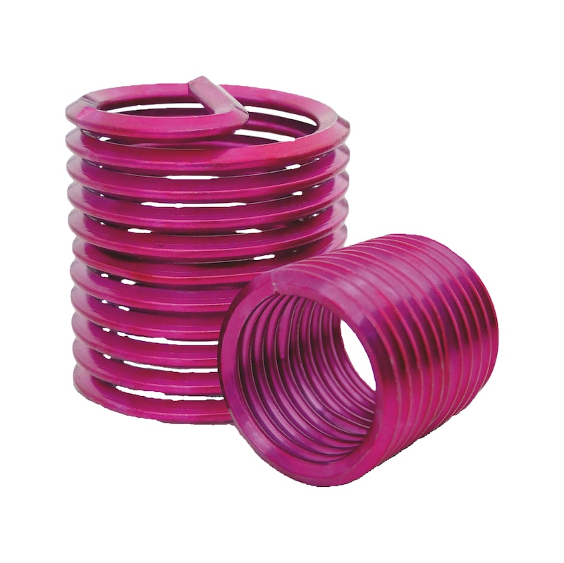
Wire thread insert SG A2 W.TEC series
HELCINRT-SG-A2-M16X16


Register now and access more than 125,000 products
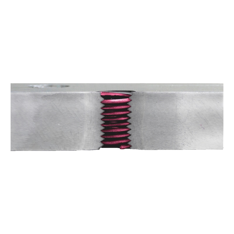
Perfect combination of space-spacing and wear-resistant thread strength
- In low-strength metal materials
- In plastics
Optimal force distribution
Flexibility of the thread inserts compensates for pitch and angle errors
Thread insert sits securely
Minimised thread friction torque and minimised torsional stress
Increased corrosion resistance
Space and weight minimisation
Smaller number of required connection points and/or reduced screwing dimensions
Costs minimised
By reinforcing the thread, which effectively minimises the repair costs
Integrated loss protection
The clamping torques are comparable with the values of DIN 267 Part 15 or DIN EN ISO 2320.
The clamping torques are comparable with the values of DIN 267 Part 15 or DIN EN ISO 2320.
Datasheets(X)
CAD data (available after login)
A resistant thread in 4 steps:
Step 1:
Drill a core hole or drill out the damaged thread
Step 2:
Create a receiving thread
- By cutting using screw tap
OR
- Without cutting using thread moulding for an even more resilient receiving thread
Step 3:
Set the thread insert
- The helical insert can be mounted both mechanically and also by hand using the corresponding screw-in tool.
Step 4:
Break the pin
- Separate the follower pin by tapping gently on the predetermined break point with a pin breaker, and then remove. Automatic pin breakers are also available for series production.
 | |
Material | Stainless steel A2 |
Surface | Plain |
Design | With loss-preventing retainer |
Thread type x nominal diameter | M16 |
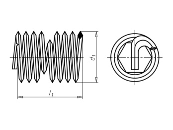
Length built-in state (l1) | 16 mm |
Outer diameter (d1) | 18.5 mm |
Thread form | Standard metric thread |
Pitch | 2 mm |
Core hole diameter | 16.5 mm |
Min. core hole depth | 25 mm |
Required thread depth at stud hole | 23 mm |
Locking device operating principle | Clamping by thread geometry |
Locking function | Locking against loosening by clamping |


