


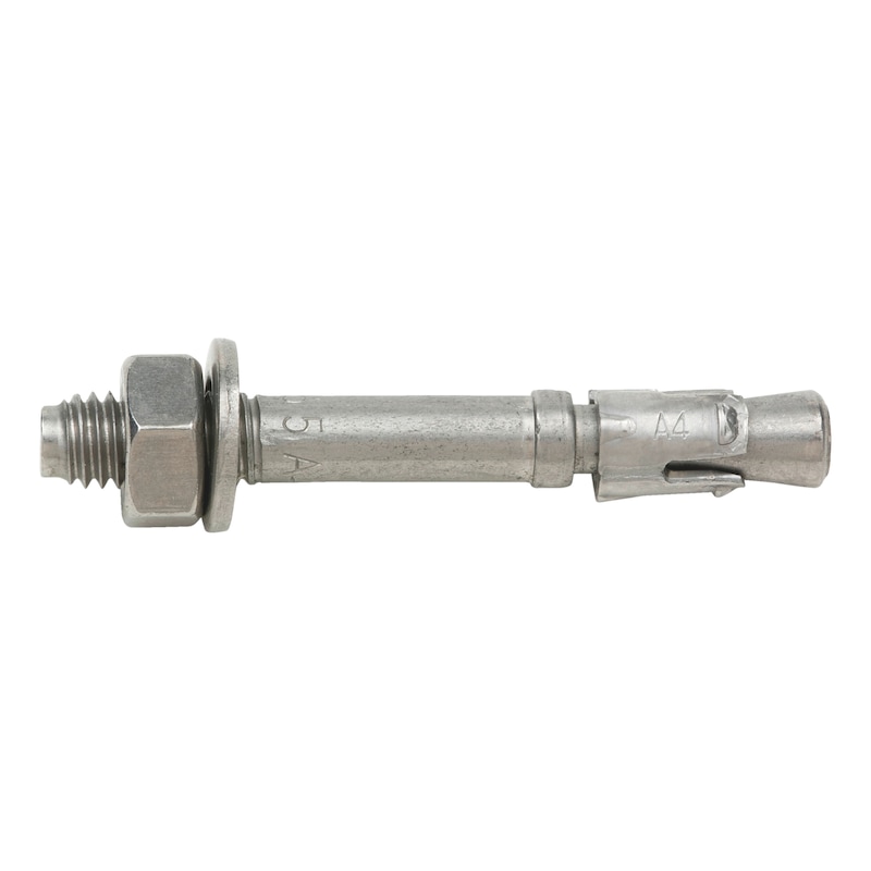


Nail anchor W-NA/A4 with M6 thread
ANC-(W-NA/A4)-A4-5-6X49
Art.-no. 0905372005
EAN 4053479285078


Register now and access more than 125,000 products
- Quick and easy installation.
- Less drilling required due to reduced effective embedment depth of 25 mm.
- Easy insertion: Simply hammer in - no torque required.
- No special drills or setting tools required.
- Push-through installation
- Very low edge distances and spacings possible.
- Load-controlled expansion anchor - expands when subjected to load.
- Anchors in a redundant non-structural system in concrete: European Technical Approval ETA-11/0339.
- Fire resistance: R30, R60, R90, R120 (base material: concrete C20/25 to C50/60): Technical Report TR 020 "Evaluation of anchorages in concrete concerning resistance to fire" (included in ETA-11/0339).
- Fire-tested in accordance with the ZTV tunnel fire curve in the cracked tensile zone.
The nail anchor offers the benefits of a bolt anchor while also being easy to install; the nail anchor is simply knocked into the drill hole through the attached part.
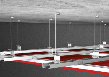 Suspended ceilings
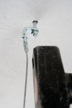
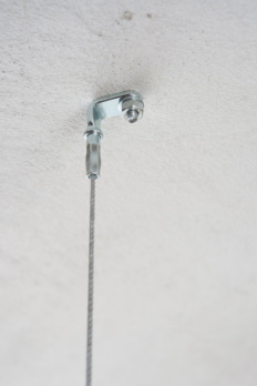
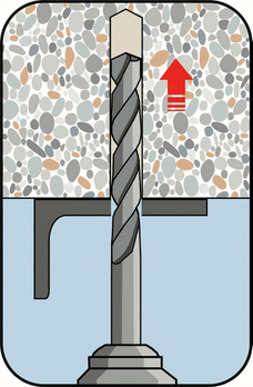
Create the drill hole
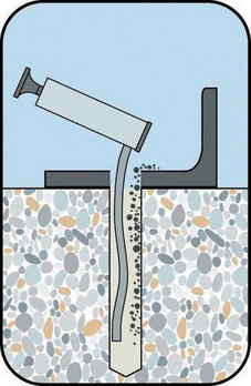
Clean the drill hole
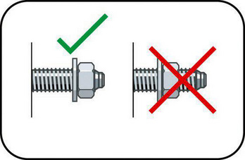
Check the position of the nut
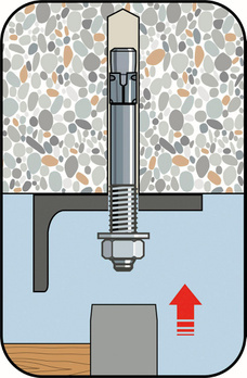
Insert W-NA through component and drive in
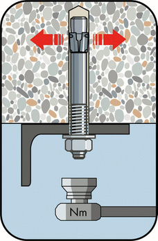
Apply torque Tinst ≤ 4 Nm
- Anchors in a redundant non-structural system in concrete: European Technical Approval ETA-11/0339.
- Fire resistance: R30, R60, R90, R120 (base material: concrete C20/25 to C50/60): Technical Report TR 020 "Evaluation of anchorages in concrete concerning resistance to fire" (included in ETA-11/0339).
- Fire-tested in accordance with the ZTV tunnel fire curve in the cracked tensile zone.
Datasheets(X)

Anchors in a redundant non-structural system in non-load-bearing systems with approval in cracked concrete (tensile zone) and uncracked concrete (compression zone)
- E.g. lightweight ceiling cladding and suspended ceilings, pipes, cable trays, metal profiles, perforated strips, wire hangers, vernier hangers, wooden strips, wooden laths, square timbers etc.
- For use in reinforced or non-reinforced normal weight concrete with a concrete compressive strength of min. C12/15 and max. C50/60 in accordance with EN 206-1:2000-12
Can be used outdoors (including in industrial atmospheres and coastal areas) or in wet rooms.
Anchor diameter | 6 mm |
Anchor length (l) | 49 mm |
Min./max. height of the fixture (t fix) | 5-10 mm |
Nominal drill-bit diameter (d 0) | 6 mm |
Effective anchoring depth (h ef) | 30 mm |
Effective anchoring depth reduced (h ef, red) | 25 mm |
Drill hole depth (h 0) | 40 mm |
Drill hole depth reduced (h 0, red) | 35 mm |
Minimum component thickness (h min) | 80 mm |
Through-hole in the component to be connected (d f) | 7 mm |
Material | Stainless steel A4 |
Surface | Plain |
| Performance data | ||
| Anchor diameter [mm] | 6 (hef [mm] = 30) | |
| Anchors in concrete in a non-structural system based on a redundant design (for all load directions) for c ≥ 100 mm and s ≥ 200 mm | Fadm [kN] ≥ C12/15 | 1.93) |
| Fadm [kN] ≥ C20/25 and ≤ C50/601) | 2.83) | |
| Anchors in concrete in a non-structural system based on a redundant design (for all load directions) for c ≥ 50 mm and s ≥ 100 mm | Fadm [kN] ≥ C12/15 | 1,0 |
| Fadm [kN] ≥ C20/25 and ≤ C50/601) | 1,2 | |
| Adm. load under exposure to fire (Technical Report TR 020) for spacing and edge distances, see European Technical Assessment ETA-11/0039 | R30; Fperm [kN]2) | 0,9 |
| R60; Fperm [kN]2) | 0,9 | |
| R90; Fperm [kN]2) | 0,9 | |
| R120; Fperm [kN]2) | 0,7 | |
| Permissible bending moment | Madm [Nm] | 7,3 |
| 1) The partial safety factors of the resistances regulated in the approval and a partial safety factor of the actions of γF = 1.4 have been taken into account. For information on combining tensile and shear loads, on the influence of the edge distance, and on anchor groups, please refer to the European Technical Approval Guidelines (ETAG), Annex C. 2) The partial safety factors for the load capacity when exposed to fire of γM,fi = 1.0, as recommended in the approval, and the partial safety factor of the actions of γF = 1.0 have been taken into account. 3) Number of attachment points ≥ 3 and at least 1 anchor per attachment point results in a load per attachment point of Fadm ≤ 1.4 kN or number of attachment points ≥ 4 and at least 1 anchor per attachment point results in a load per attachment point of Fadm ≤ 2.1 kN. The admissible loads can be increased if the design shows that the requirements governing the strength and rigidity of the component to be attached remain satisfied even after the failure of an anchor in terms of the limit state of serviceability and load capacity. | ||
| Characteristic values | ||
| Minimum member thickness | hmin [mm] | 80 |
| Effective anchorage depth | hef [mm] | 30 |
| Nominal drill ∅ | d0 [mm] | 6 |
| Diameter of cutting edges | dcut ≤ [mm] | 6,4 |
| Drill hole depth | h1 ≥ [mm] | 40 |
| Through hole in the component being connected | df ≤ [mm] | 7 |
| Torque while installing anchor | Tinst ≤ [Nm] | 4 |
Select RAL-colour code
!! NOTE: On-screen visualisation of the colour differs from real colour shade!!
Last viewed

Traffic cone, 2 pieces

Hexagon bolt with thread up to the head ISO 4017, steel 8.8, zinc-plated, blue passivated (A2K)

Hexagon socket set screw with pin ISO 4028, steel, 45H, zinc-plated, blue passivated (A2K)

Hexagon bolt with thread up to the head ISO 4017, steel 8.8, plain

Welding protection cassette SR 84 Sundström T01-1212

Arrow-shaped floor marking

Work dungarees Kübler Vita Mix 3L47 5365

Control valve Sundström R03-1426

Hexagon head bolt With collar, Hygienic USIT®

Hexagonal nut DIN 934, zinc plated I8I steel with thick-layer passivation (VZD)