Anchor clamp, screw-in
For detailed information, other images and documents, please select individual articles from the following table.
Anchor clamp, screw-in
Anchor clamp with screw fixing for lifting loads
Exclusively for trade customers
Register now and access more than 125,000 products


Variants
Exclusively for trade customers
Register now and access more than 125,000 products
- Guaranteed hold without welding
- Safety factor 4
- Ring can be adjusted 120°
- Screw with hex head, black burnished, strength class 10.9 according to standard UNI 5739/DIN 933
- Screw, bracket and ring are 100% crack-tested
- Made of high-strength steel
- Painted with epoxy paint, in RAL 3022
- Strength class 10
Proof of Performance
Suitable for safe lifting in accordance with Machine Directive 2006/42/EC.
Designed for a load of 20,000 load changes.
Notice
- Screw included in scope of delivery
- Only suitable for lifting loads – not persons
- Check the suitability of the strength class of the female thread for accommodating the clamp in comparison to the load to be lifted. The material of the female thread must demonstrate a tensile strength that is the same as or greater than that of steel S235JR (criterion EN 10025)
- Check whether the contact surface of the female thread is suitable in terms of evenness and size
- The depth of the thread bore must be at least: 1 x D for steel 1.25 x D for cast iron 2 x D for aluminium alloys 2.5 x D for aluminium-magnesium alloys
- The thread bore must run at right angles to the contact surface
- For the installation of the clamp, it is sufficient to tighten the screw with a wrench, no extensions may be used as you could overload the screw with excessive tightening torque (do not exceed the tightening torques indicated in the table). For removal, follow the procedure in reverse order.
- The clamp must always stay oriented to the tensile direction
- The ring must turn within the clamp freely and without obstructions
- Check the strength of the screws after an extended period of use
| Art. no. | Max. load-carrying capacity | 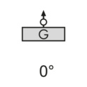 | 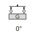 | 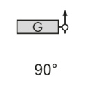 | 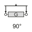 | 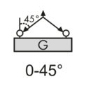 | 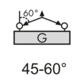 | 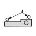 | 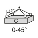 | 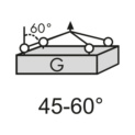 | 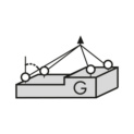 |
| W.L.L. | 1 chain | 2 chains | 1 chain | 2 chains | 2 chains | 3/4 chains | |||||
| 5162 127 20 | 4 t | 4 t | 8 t | 4 t | 8 t | 5.6 t | 4 t | 4 t | 8.4 t | 6 t | 4 t |
| 5162 127 24 | 6.7 t | 6.7 t | 13.4 t | 6.7 t | 13.4 t | 9.5 t | 6.7 t | 6.7 t | 14 t | 10 t | 6.7 t |
| 5162 127 30 | 10 t | 10 t | 20 t | 10 t | 20 t | 14 t | 10 t | 10 t | 21 t | 15 t | 10 t |
| 5162 127 36 | 16 t | 16 t | 32 t | 16 t | 32 t | 22.4 t | 16 t | 16 t | 33.6 t | 24 t | 16 t |
Suitable for safe lifting in accordance with Machine Directive 2006/42/EC.
Designed for a load of 20,000 load changes.
Select RAL-colour code
!! NOTE: On-screen visualisation of the colour differs from real colour shade!!


