


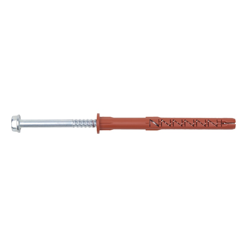

W-UR 14 F SYMCON plastic frame fixing with zinc plated steel hexagon head screw, flat collar and SYMCON thread
ANC-(W-URF SYM)-RW50-(A2K)-80-110-14X180
Art.-no. 0912814605
EAN 4050642351578


Register now and access more than 125,000 products
Reliable and quick
- Reliable follow-up expansion capability due to ingenious fixing geometry.
- The teeth expand in four directions and claw firmly into the base material.
- Fixing via friction locking between fixing sleeve and base material.
- High admissible loads due to expansion in four directions.
- Improved load transmission through even, continuous load transfer across the entire expansion area.
- Virtually no spinning of the fixing sleeve due to low installation torque and expansion.
- Fixing sleeve made of high-quality polyamide.
- Very strong anti-rotation lock.
- Does not require an additional washer and prevents contact corrosion.
Intuitive installation
- Time-saving due to immediate load-bearing capacity.
- Less installation work, as the fixing sleeve and special screw are pre-assembled.
- Hammer-in stop prevents premature expansion of the fixing during installation.
Multiple embedment depths
- Masonry: 2 embedment depths (50 mm and 70 mm)
- Concrete: 3 embedment depths (40 mm, 50 mm and 70 mm)
European Technical Approval ETA-11/0309, multiple attachment of non-load-bearing systems in concrete and masonry
- When anchoring in solid brick and solid sand-lime block, we recommend performing pull-out tests due to differences in brick manufacturing.
- Lengths 330 mm, 360 mm and 390 mm are not pre-assembled.
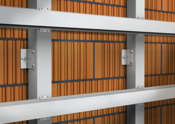 Metal substructures
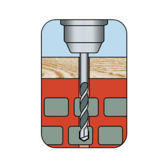 Create the drill hole
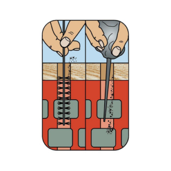 Clean the drill hole
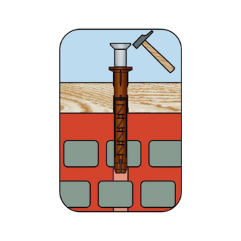
Set anchor and screw
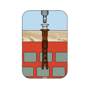
Screw in the screw
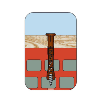
Screw in screw until flush
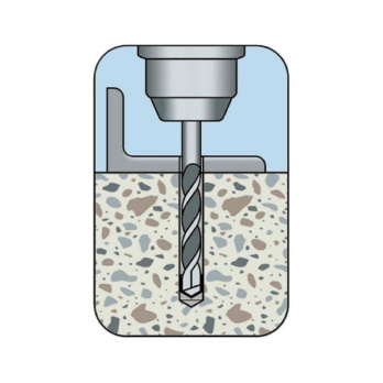 Create the drill hole
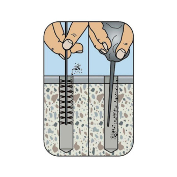 Clean the drill hole
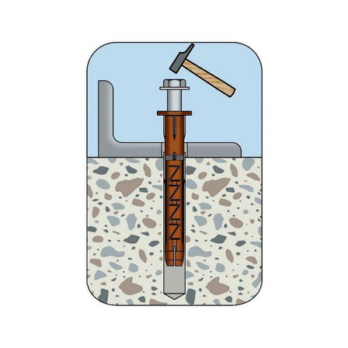 Set anchor and screw
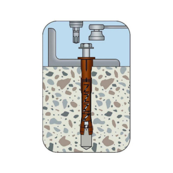 Screw in the screw
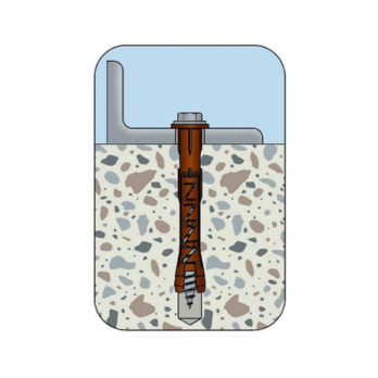 Screw in screw until flush
European Technical Approval ETA-11/0309, multiple attachment of non-load-bearing systems in concrete and masonry
Datasheets(X)

- Suitable for fastening façades, suspended ceilings, roof substructures made of wood or steel, wooden beams, wooden laths, angle brackets, wall-mounted cabinets, shelves etc.
- Suitable for anchoring in normal weight concrete masonry walls such as solid brick, solid sand-lime blocks, vertically perforated brick, hollow sand-lime blocks, hollow lightweight concrete blocks, solid lightweight concrete blocks, concrete bricks
- Drill perforated and hollow concrete blocks with a rotary drill (without hammer mechanism)
- Drill cuttings must be removed from the drill hole
- Installation temperature in base material ≥ -20 °C
- Installation temperature of the anchor sleeve ≥ 0 °C
Anchor diameter | 14 mm |
Anchor length (l) | 180 mm |
Nominal drill-bit diameter (d 0) | 14 mm |
Through-hole in the component to be connected (d f) | 14.5 mm |
Attachment height (t fix 1) | 110 mm |
Material of screw | Steel |
Internal drive | RW50 |
Surface of the screw | Zinc plated |
Head type | Hexagon head |
Embedding depth (h nom1) | 70 mm |
Approval | ETA-11/0309 |
Type description | W-UR F 14 SymCon, hexagonal bolt |
| Performance data: Concrete, anchors in a redundant non-structural system | ||||
| Anchor diameter | [mm] | W-UR 14 SymCon | ||
| Embedment depth of the anchor sleeve | hnom [mm] | 70 | 100 | |
| Centric tension load1) for individual anchors or an anchor group | Nadm = C12/15 [kN] | 30°C2)/50°C3) | 2,4 | 2,4 |
| 50°C2)/80°C3) | 2,2 | 2,4 | ||
| Nadm ≥ C16/20 [kN] | 30°C2)/50°C3) | 3,2 | 3,2 | |
| 50°C2)/80°C3) | 3,0 | 3,2 | ||
| Shear load1) for individual anchors or an anchor group | Vadm | [kN] | 9,5 | 9,5 |
| Minimum member thickness | hmin | [mm] | 110 | 140 |
| Minimum axis distance4) | smin [mm] | C12/15 | 85 | 85 |
| ≥ C16/20 | 60 | 60 | ||
| Minimum edge distance4) | cmin [mm] | C12/15 | 115 | 115 |
| ≥ C16/20 | 80 | 80 | ||
| Characteristic edge distance | ccr,N [mm] | C12/15 | 110 | 140 |
| ≥ C16/20 | 80 | 100 | ||
| 1) The partial safety factors of the resistances regulated in the approval and a partial safety factor of the actions of γF = 1.4 have been taken into account. For information on combining tensile and shear loads, please refer to ETAG 020 Annex C. 2) Maximum long-term temperature. 3) Maximum short-term temperature. 4) The admissible load must be reduced. | ||||
Installation parameters: Concrete + masonry | |||
Anchor diameter [mm] | W-UR 14 SymCon | ||
| Nominal drill diameter | d0 [mm] | 14 | |
| Drill cutting dia. | dcut ≤ [mm] | 14,45 | |
| Drill hole depth | h1 ≥ [mm] | 80 | 110 |
| Embedment depth of the anchor sleeve | hnom [mm] | 70 | 100 |
| Through hole in the attachment | df ≤ [mm] | 14,5 | |
| Total length L [mm] | Fixture thickness tfix [mm] | Embedment depth hnom [mm] | Drill hole depth h1 [mm] |
| 80 | 10/- | 70/- | 80 (+tfix)/110 (+tfix) |
| 110 | 40/10 | 70/100 | |
| 140 | 70/40 | ||
| 160 | 90/60 | ||
| 180 | 110/80 | ||
| 210 | 140/110 | ||
| 240 | 170/140 | ||
| 270 | 200/170 | ||
| 300 | 230/200 | ||
| 330 | 260/230 | ||
| 360 | 290/260 | ||
| 390 | 320/290 |
| Performance data: Masonry4), anchors in a redundant non-structural system (temperature range 50°C2)/80°C3)) For other brick types, raw densities, minimum compressive strengths, edge and axis distances or temperature ranges, please refer to the approval ETA-11/0309 | |||||
| Brick type | Brick format [mm] | Raw density class [kg/dm³] | Minimum compressive strength [N/mm²] | Fadm [kN]1)5) (for individual anchors or an anchor group) W-UR 14 SymCon | |
| Effective anchorage depth | hnom [mm] | 70 to 99 | 100 | ||
| Masonry brick Mz, EN 771-1, DIN 105 | ≥ 3DF (≥ 240 x 115 x 113) | ≥ 1.8 | 10 | - | 1,0 |
| 20 | - | 1,57 | |||
| Solid sand-lime brick Silka XL Basic, Silka XL Plus, EN 771-2, DIN 106, Z-17.1-997 | ≥ NF (≥ 248 x 175 x 498) | ≥ 2.0 | 10 | 0,86 | 0,86 |
| 20 | 1,29 | 1,29 | |||
| 28 | 1,71 | 1,86 | |||
| Normal weight concrete solid brick Vbn, EN 771-3, DIN 18153 | ≥ NF (≥ 240 x 115 x 71) | ≥ 2.0 | 10 | - | 0,57 |
| 20 | - | 0,86 | |||
| 28 | - | 1,14 | |||
| Normal weight concrete solid brick V, EN 771-3, DIN 18152-100 e.g. BisoBims Classic, Bisotherm | ≥ 3DF (≥ 240 x 115 x 113) | ≥ 2.0 | 10 | - | 1,14 |
| 20 | - | 1,57 | |||
| Lightweight concrete solid brick V, EN 771-3, DIN 18152-100 e.g. BisoBims | ≥ NF (≥ 240 x 115 x 71) | ≥ 1.0 | 2 | - | 0,34 |
| 4 | - | 0,57 | |||
| Vertically perforated brick HLz6), EN 771-1, DIN 105 e.g. Wienerberger, Schlagmann | ≥ 12DF (≥ 373 x 240 x 238) | ≥ 1.2 | 6 | - | 0,43 |
| 8 | - | 0,57 | |||
| 10 | - | 0,71 | |||
| Vertically perforated brick HLz T14-24.06), EN 771-1, Z-17.1-651 e.g. Wienerberger | ≥ 10DF (≥ 308 x 240 x 249) | ≥ 0.7 | 6 | - | 0,17 |
| Vertically perforated brick POROTON T8-306), POROTON T9-306), EN 771-1, T8: Z-17.1-982, T9: Z-17.1-674 Wienerberger, Schlagmann | ≥ 10DF (≥ 248 x 300 x 249) | ≥ 0.6 | 6 | - | 0,43 |
| 8 | - | 0,57 | |||
| Vertically perforated brick POROTON S106), EN 771-1, Z-17.1-1017 Wienerberger, Schlagmann | ≥ 10DF (≥ 248 x 300 x 249) | ≥ 0.75 | 8 | - | 0,43 |
| Vertically perforated brick POROTON S11-306), EN 771-1, Z-17.1-812 Wienerberger, Schlagmann | ≥ 10DF (≥ 248 x 300 x 249) | ≥ 0.9 | 8 | - | 0,71 |
| Vertically perforated brick ThermoPlan MZ106), EN 771-1, Z-17.1-1015 Mein Ziegelhaus | ≥ 10DF (≥ 248 x 300 x 249) | ≥ 0.75 | 8 | 0,5 | 0,71 |
| Vertically perforated brick ThermoPlan TS2)6), EN 771-1, Z-17.1-993 Mein Ziegelhaus | ≥ 9DF (≥ 373 x 175 x 249) | ≥ 0.9 | 6 | 0,11 | 0,11 |
| 8 | 0,17 | 0,17 | |||
| 10 | 0,21 | 0,21 | |||
| 12 | 0,26 | 0,26 | |||
| 20 | 0,43 | 0,43 | |||
| Vertically perforated brick THERMOPOR TV 9-Plan6), EN 771-1, Z-17.1-1006 Thermopor Ziegel-Kontor Ulm | ≥ 247 x 300 x 249) | ≥ 0.75 | 4 | - | 0,26 |
| 6 | - | 0,43 | |||
| 8 | - | 0,57 | |||
| Hollow sand-lime brick KSL6), EN 771-2, DIN 106-1 e.g. Xella | ≥ 8DF (≥ 248 x 240 x 238) | ≥ 1.4 | 6 | - | 0,34 |
| 8 | - | 0,43 | |||
| 10 | - | 0,57 | |||
| 12 | - | 0,71 | |||
| Hollow concrete block made of lightweight concrete 3K Hbl, EN 771-3, DIN 181516) e.g. Liapor | ≥ 16DF (≥ 498 x 240 x 238) | ≥ 0.7 | 2 | - | 0,14 |
| 4 | - | 0,26 | |||
| 6 | - | 0,43 | |||
| 1) The partial safety factors of the resistances regulated in the approval and a partial safety factor of the actions of γF = 1.4 have been taken into account. For information on combining tensile and shear loads, please refer to ETAG 020 Annex C. 2) Maximum long-term temperature. 3) Maximum short-term temperature. 4) For other brick types, raw densities, minimum compressive strengths or temperature ranges, please refer to the approval ETA-11/0309. 5) The brick geometry should be compared with the approval ETA-11/0309. 6) If the drill hole is created through impact or hammer action, the admissible load must be determined by tests on the structure. | |||||
Last viewed

EU+ HSCo 90° countersink DIN 335 C

ANG 18 nozzle

Thread mandrel for PEG 312

Scraper blade

SHARK plastic multi-purpose anchor without collar

Top Dos measuring cup

Strip for Twin-Fixx quick-mount number plate holder, printed

Strip for Twin-Fixx quick-mount number plate holder, printed

Strip for Twin-Fixx quick-mount number plate holder, printed

Digital calliper RW Edition